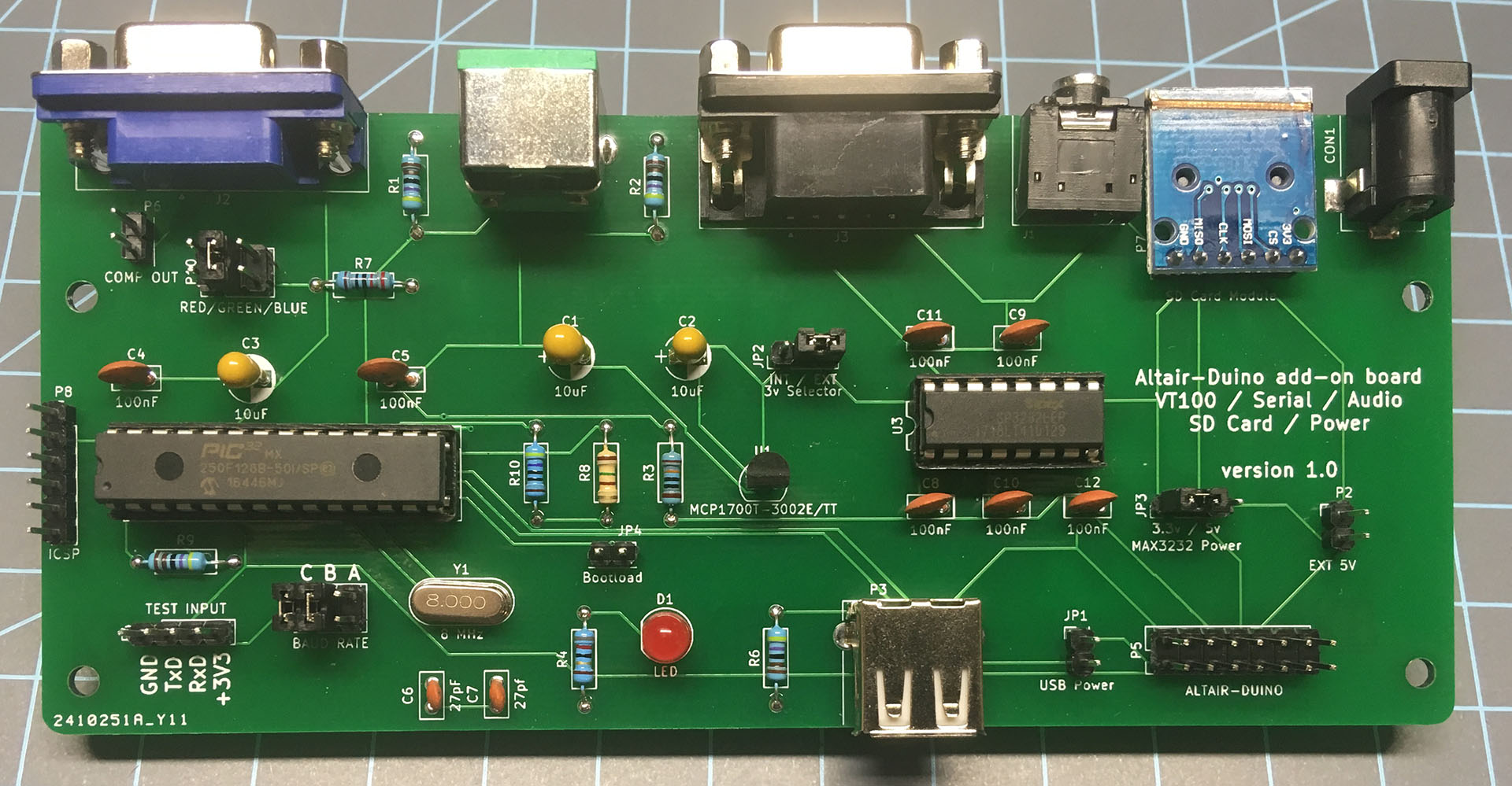
You no doubt noticed that there are jumpers on the I/O Expansion board. What do they do? Read on!
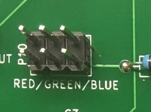
- Location P10 is the color selector for the VGA output. I'd suggest selecting only one color. You can jumper more than one (eg. jumper Red, Green, and Blue for white) but this may result in a dim display, depending on your monitor.
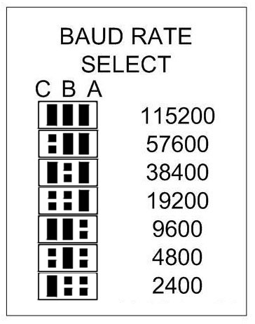
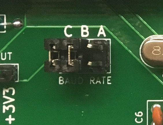
- Location P9 is the baud rate selector for the VT100 emulation. The default setting (pictured) is 9600 baud. Here is a table of settings:
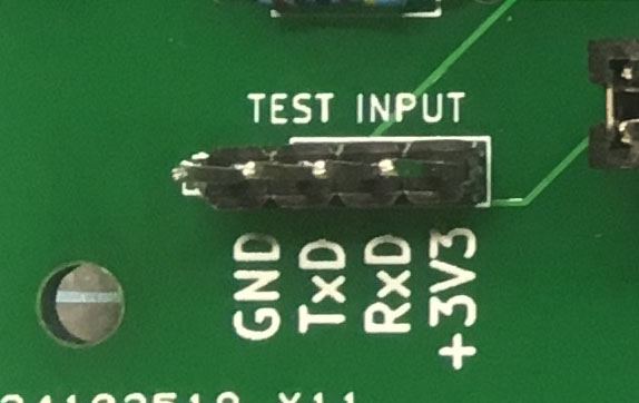
- P4 is the TTL serial data from pin 18/19 on the Arduino. If you remove the PIC32 microcontroller, you can connect a MAX3232 serial module to these pins and use it as Serial port 1 on the Altairduino.
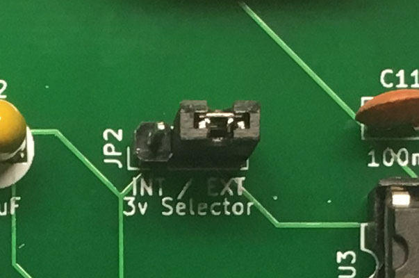
- JP2 selects the source of 3.3v for the VT100 emulator. When the I/O expansion is connected to the main board, this should ALWAYS be set to EXT (meaning 3.3v is provided by the Altairduino.) When you are using the I/O expansion disconnected from the Altairduino (for testing, installing upgraded firmware, or any other use) this should be set to INT (meaning 3.3v will be provided by the onboard voltage regulator.)
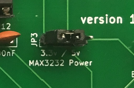
- JP3 selects the voltage supply to the MAX3232 circuit. Normally this would always be set to 3.3v. I have run across a few circumstances where garbage characters were showing when used with an older serial terminal. Setting this to 5v should make it work as expected.
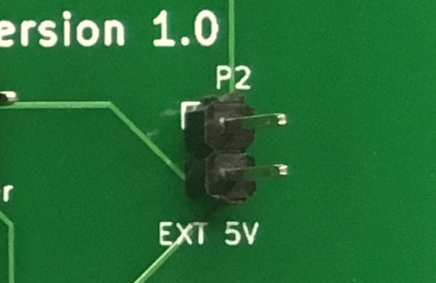
- P2 allows you to connect an external 5v power source. Be sure this is not connected to the Altairduino if you use this.
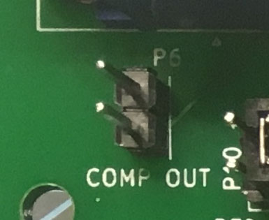
- You can connect a composite video connector to P6.
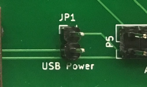
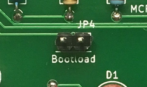
- JP1 and JP4 allow you to flash the PIC32 with new programming. To upload to the PIC32, first disconnect it from the Altairduino. Move jumper JP2 from EXT to INT. Put a jumper on JP1 to enable power from the USB port.
- Put a jumper on JP4 Bootload.
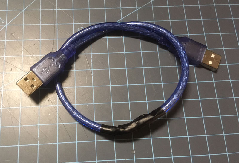
- You will need to connect the USB-A port to the USB port on your computer, which will no doubt also be a USB-A. That is an unusual cable, but you can either make it yourself if you have a couple spare cables. The wires in the cable are most likely color coded, so just connect black to black, white to white, and so on.
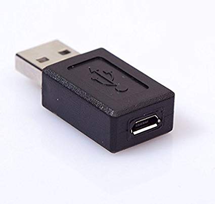
- You could also purchase an adapter, like this one I have that converts a USB Micro B female to USB A male. Connect the I/O Expansion board to your computer with the USB cable. The LED should illuminate but nothing will show on the video output. This is because the Terminal is now in upgrade (or "bootload") mode. Important: Now you should remove the jumper across the two pins marked BOOTLOAD – the LED should go out
What new programming would you upload? You can try David Hansel's VDM-1 emulator or reprogram the source code and make your own!
You can always revert the firmware to its original by following the instructions and uploading the Terminal_V1.3_UPGRADE.hex file.You can download the hex files at this link.
Download this utility and unzip it to your desktop (this is for Windows only.) Double-click to launch it. Click the "Enable" checkbox for USB and make sure 0x4D8 is the VID (it should be) and enter 0xFA8D into the PID text field. Click the connect button.
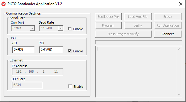
Click "Load Hex File" and select the hex file you want to upload. Once the file is loaded, click "Erase-Program-Verify". The process should take just a few moments. If something does go wrong you can always abort and restart from step 1, even if the upload was interrupted in the middle of re-flashing the memory.
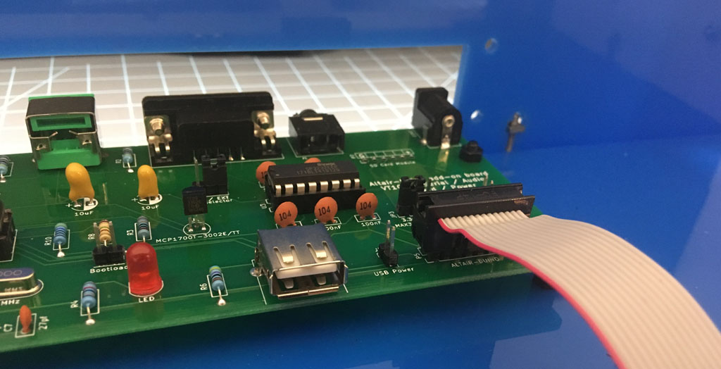
- After you're finished, remember to remove the jumper from USB Power and move JP2 back to EXT. Now you can reconnect the 14-pin ribbon cable.