
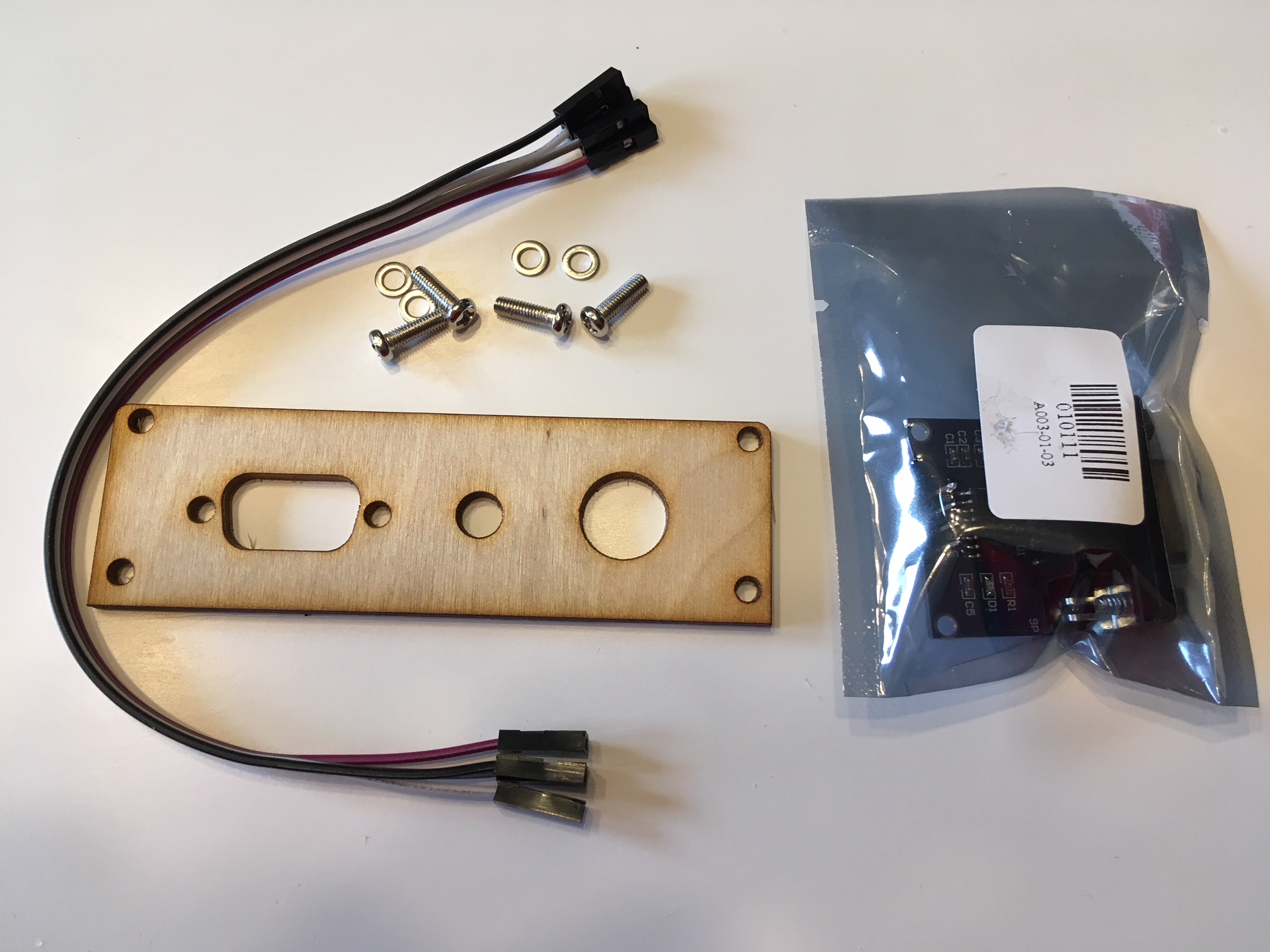
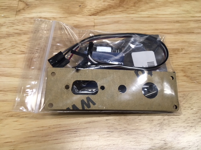
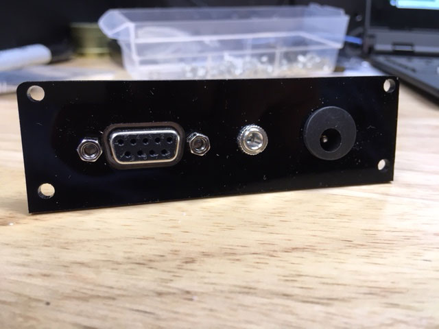
- Grab the bag with the MAX3232 module, back panel, and stainless steel screws. Your panel may be wood or acrylic.
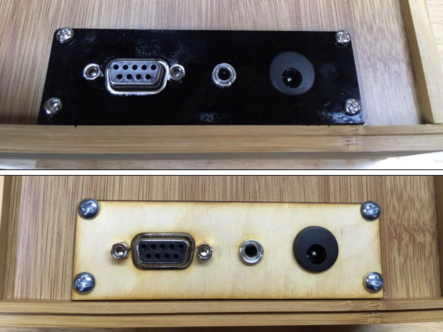
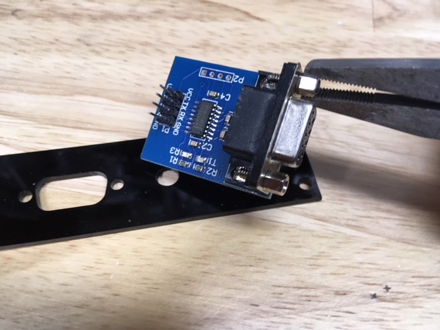
- Take your needle nose pliers and remove the screws, place the DB9 connector in the panel, and replace the screws.
- Add the audio jack and the power jack to the panel.
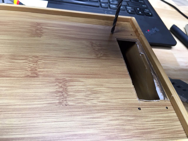
- Prepare your case for the panel. Mark off an area that is no more than 3" x 1" on the right side of the box (when looking at the front.) On this side there is a larger gap between the side of the box and the circuit board.
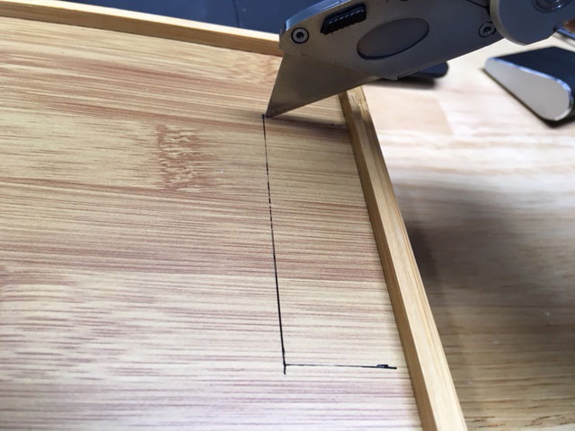
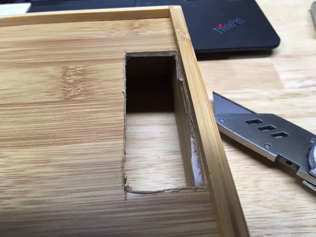
- The box will cut easily with an X-acto knife or box cutter (be careful!) Don't worry if the edges aren't clean, they will be covered.
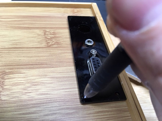
- Put the rear panel in place and mark the holes with a pen or pencil.
- Drill the holes you just marked with a 1/8" or 3mm drill bit.
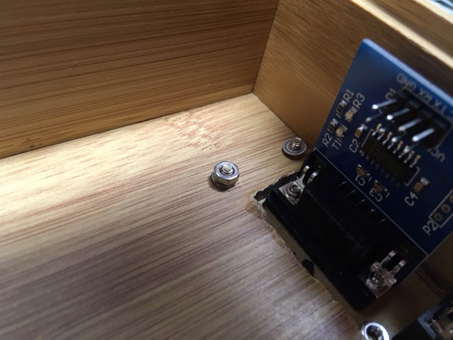
- Put the rear panel in place and attach with stainless steel screws, washers, and nuts.
- Add a four pin header for "Serial 2" to the bottom of the circuit board.
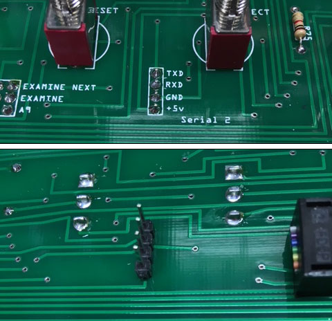
- Connect the four pin header to the MAX3232 serial module. IMPORTANT: this is not a "straight-through" connection. Pay attention to the pin labels on the board and on the serial module and connect the correct pins.
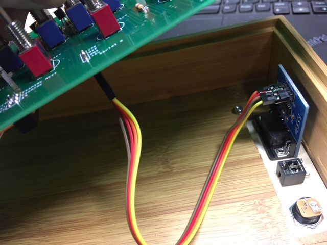
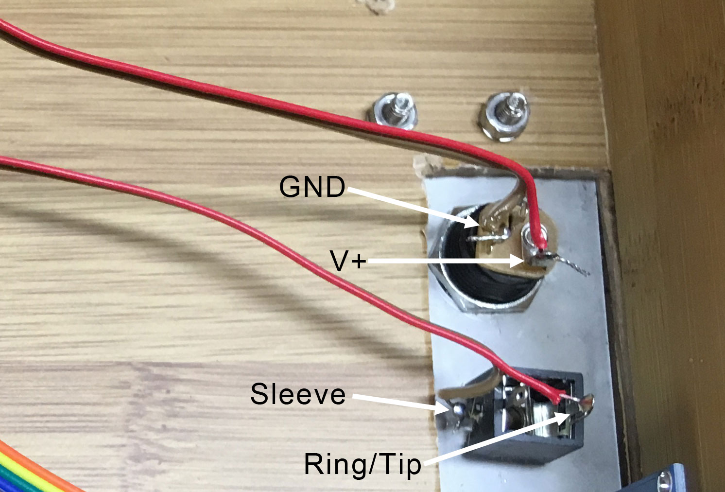
- Connect the power connector (to the V+ and GND solders pads on the left side of the board, and the audio connector to the solder pads on the right side of the circuit board (labeled "ring/tip" and "sleeve".)
- Now doesn't that look nice?