

If you prefer printed instructions, you can download and print these instructions here.
- I would strongly suggest comparing the parts you received with the list below. Let me know if you’re missing anything and I will send a replacement.
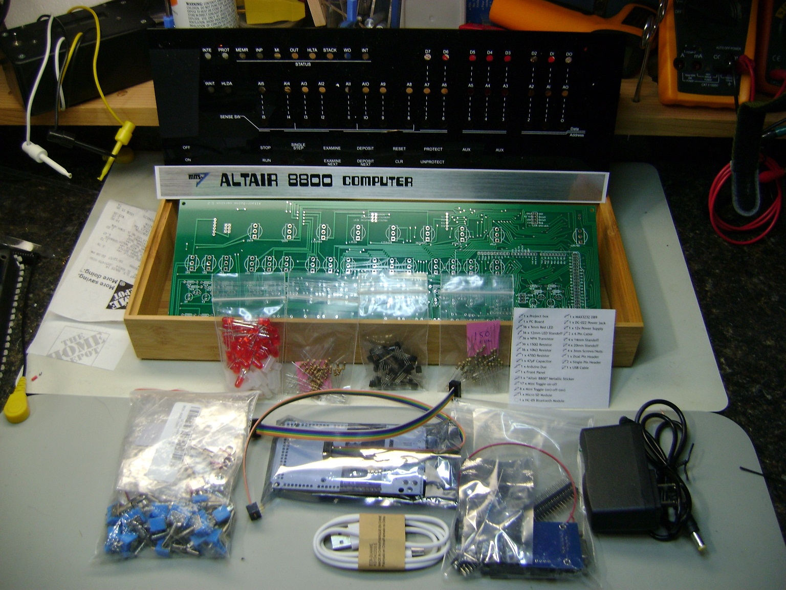
Parts List
- 1 x PC Board
- 36 x 5mm Red LED
- 36 x 12mm LED Standoff
- 36 x NPN Transistor
- 36 x 150Ω Resistor
- 36 x 10kΩ Resistor
- 17 x Mini Toggle on-off
- 8 x Mini Toggle (on)-off-(on)
- 1 x 470Ω Resistor
- 1 x 47µF Capacitor
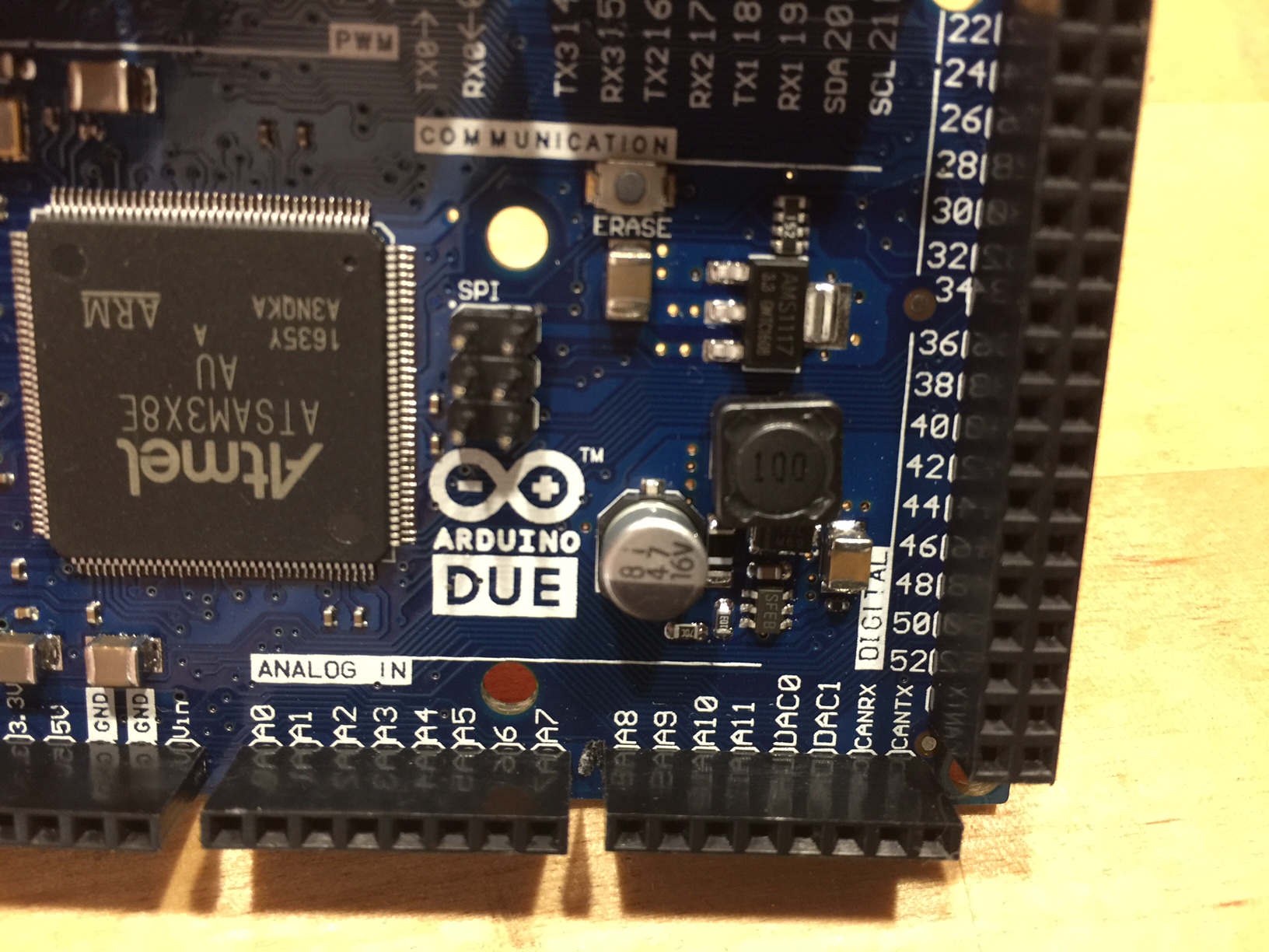
- 1 x Arduino Due
- 1 x Front Panel
- 1 x “Altair 8800” Metallic Sticker
- 1 x Project box (optional)
- 1 x Micro SD Module
- 1 x HC-05 Bluetooth Module OR 1 x MAX3232 DB9 Serial Port
- 1 x DC-022 Power jack
- 1 x 12v Power Supply
- 2 x 6 Pin Cable
- 4 x 14mm Standoff
- 4 x 20mm Standoff
- 4 x 3mm Screws
- 4 x 3mm Nuts
- 1 x Dual Pin Header
- 2 x Single Pin Header
- 1 x USB Cable
Other Parts You May Need
- Soldering Iron with a nice fine tip
- Good Solder (I recommend Alpha Fry Rosin Core 0.032” Solder)
- De-soldering Iron or Pump (optional)
- Flat Screwdriver
- Needle-nose Pliers
- Side Cutters (Nippers)
- Drill with 3mm or 1/8″ and 12mm or 1/2″ bits
- Micro SD Card (1GB is sufficient)
- Computer
If you didn’t choose to receive a pre-programmed Arduino, you will have to upload the software at some point. You can do that by following the instructions on this page.
- Start by adding 36 150Ω resistors to the top rows under the LED/Transistor pairs in locations R1-R36. Resistors are non-polarized, meaning they can go in either direction, you do not need to worry about orientation.
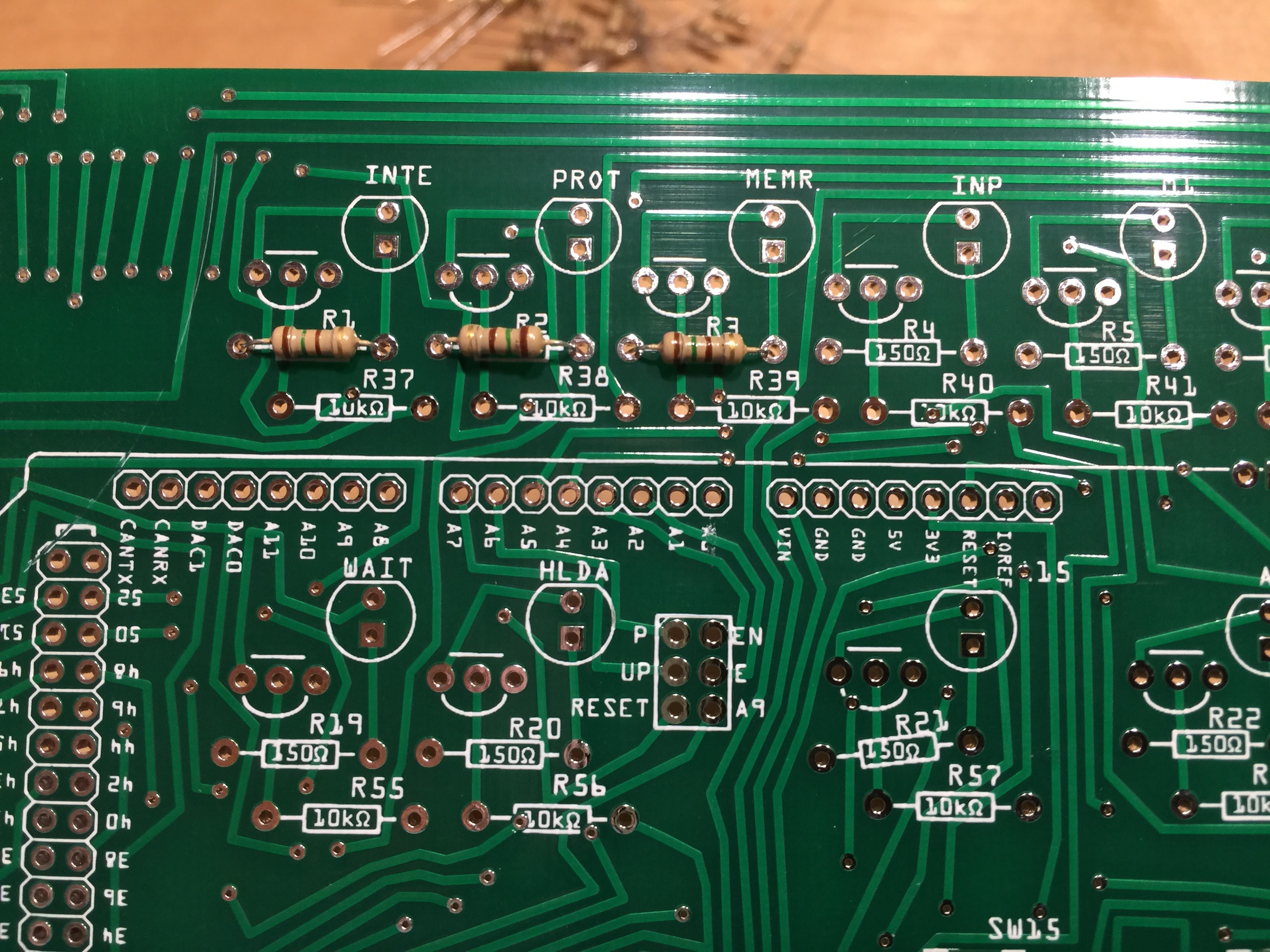
- Next, add 36 10kΩ resistors to the second row in locations R37-R72.
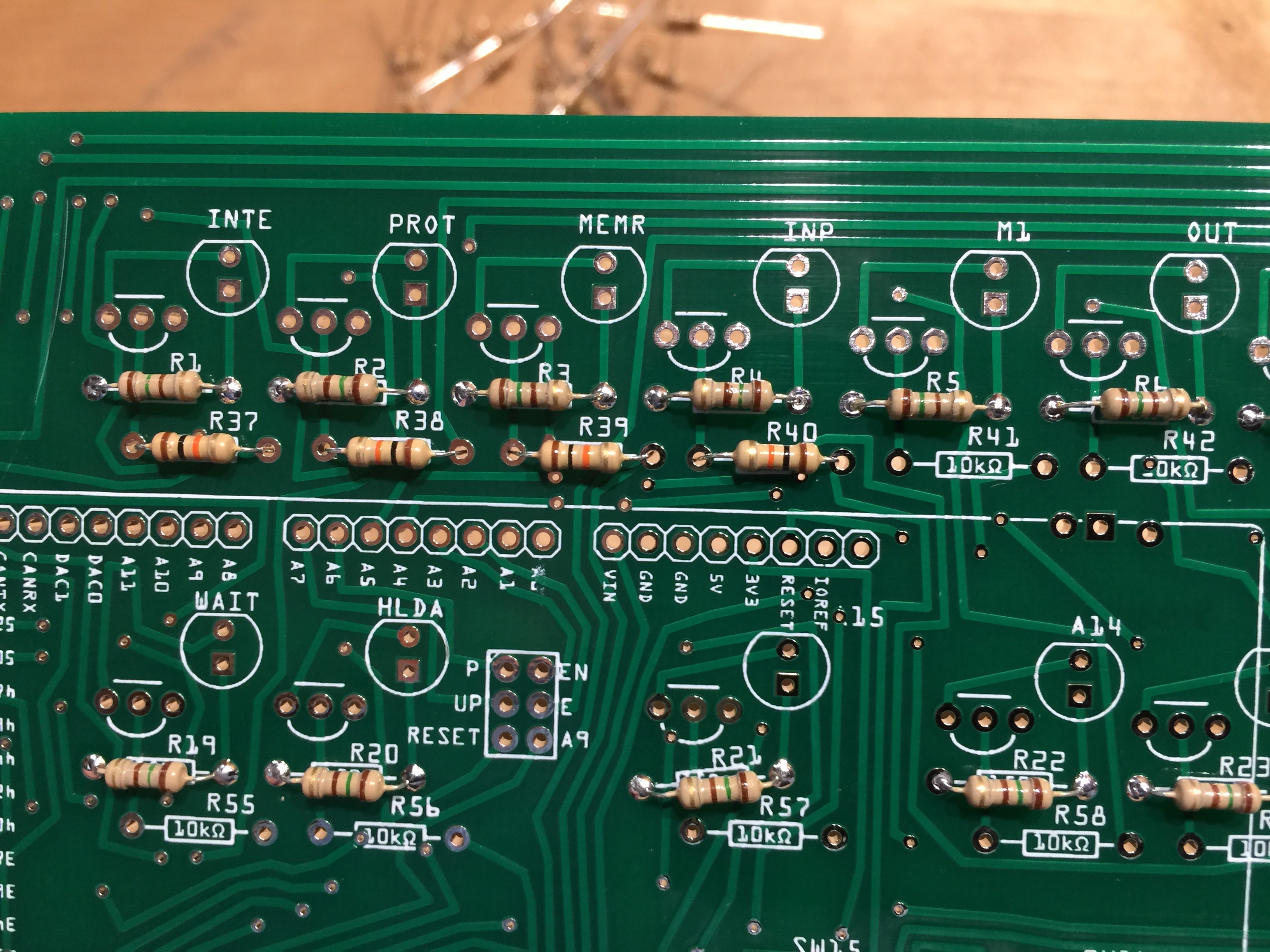
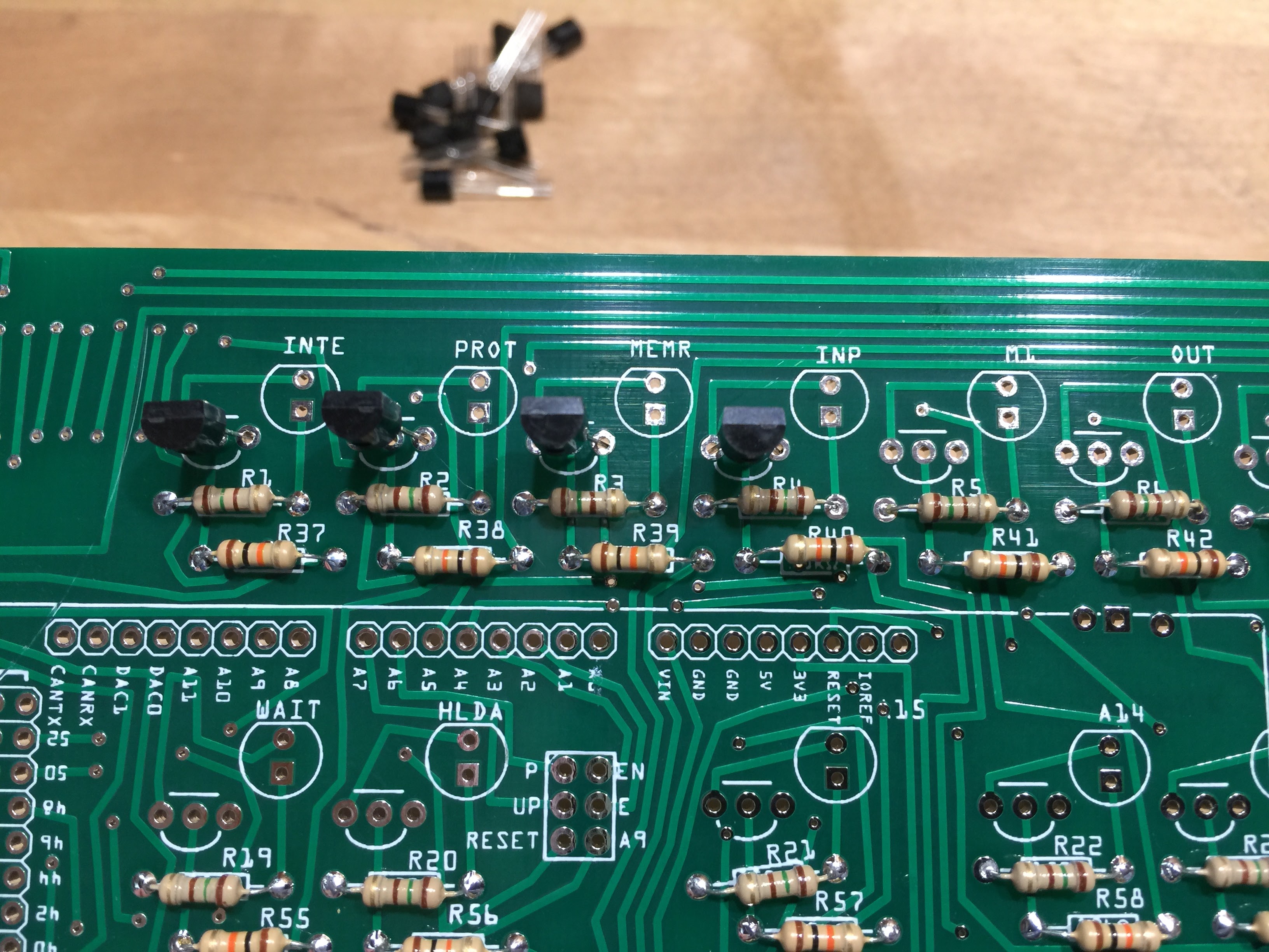
- The 36 transistors are added next. The orientation of the transistor is crucial, but relatively simple. Just make sure the flat end of the resistor is facing up, just like the image printed on the circuit board.
- Use your side cutters to clip the single pin headers into 5 segments of 8 pins, and 1 segment of 10 pins to mount the Arduino board.
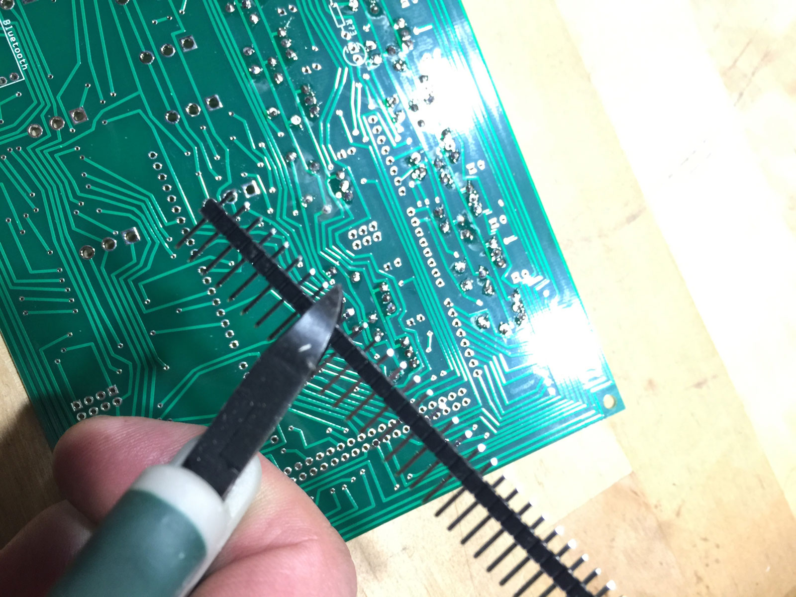
- Solder in the six single pin headers and one dual pin header. This is where a nice fine tip soldering iron and good solder are essential. This part of the circuit board is a pretty tight working area.
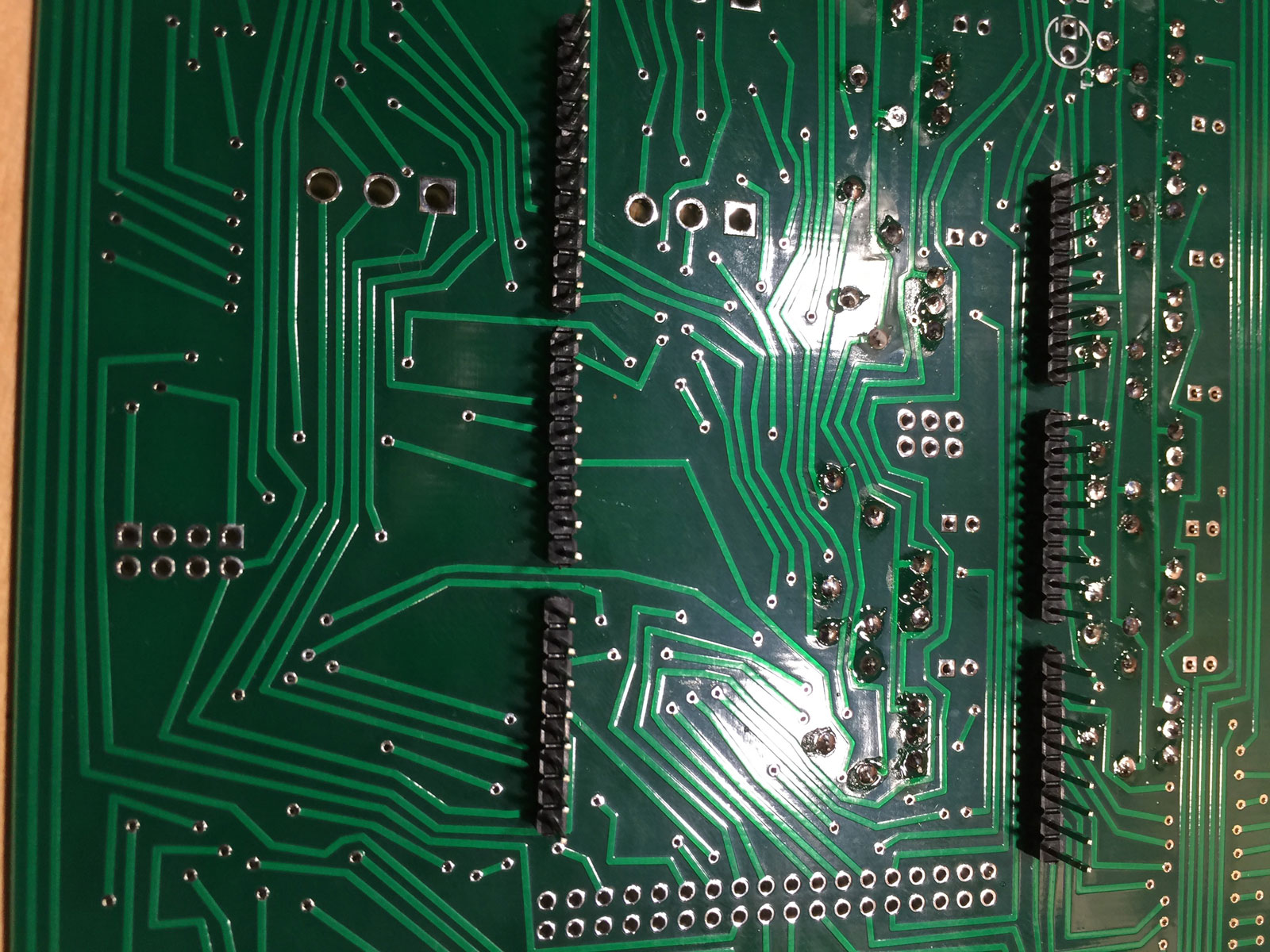
- Clip a 36-pin segments of the dual pin header and solder that to the board for the Ardunio.
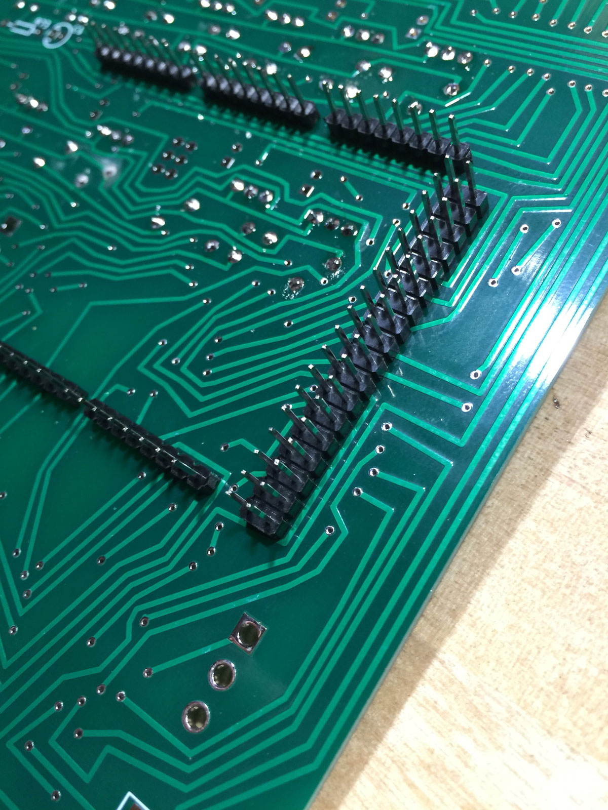
- Make sure you solder the headers facing the underside of the circuit board. Be sure to keep them as straight as you can.
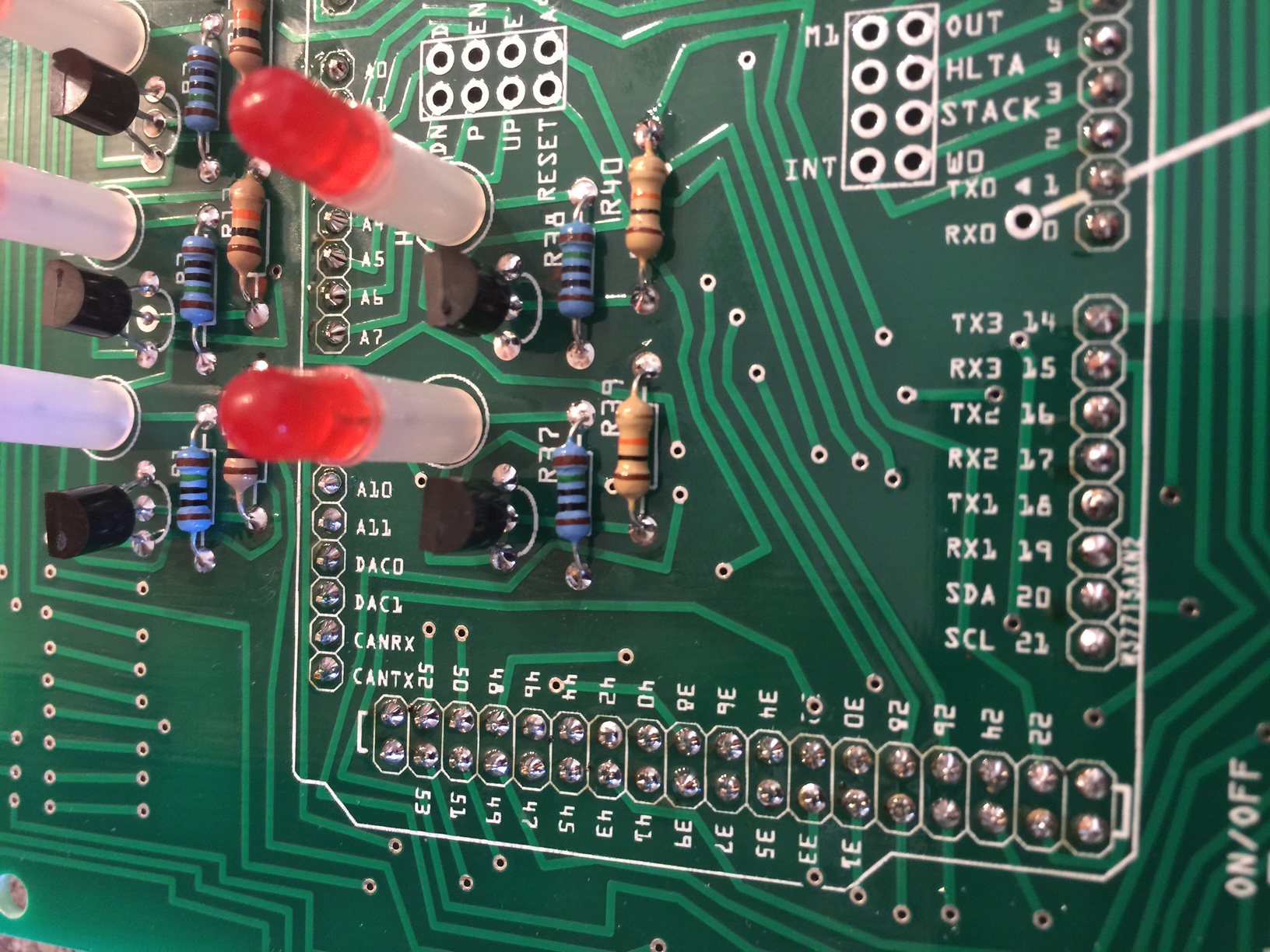
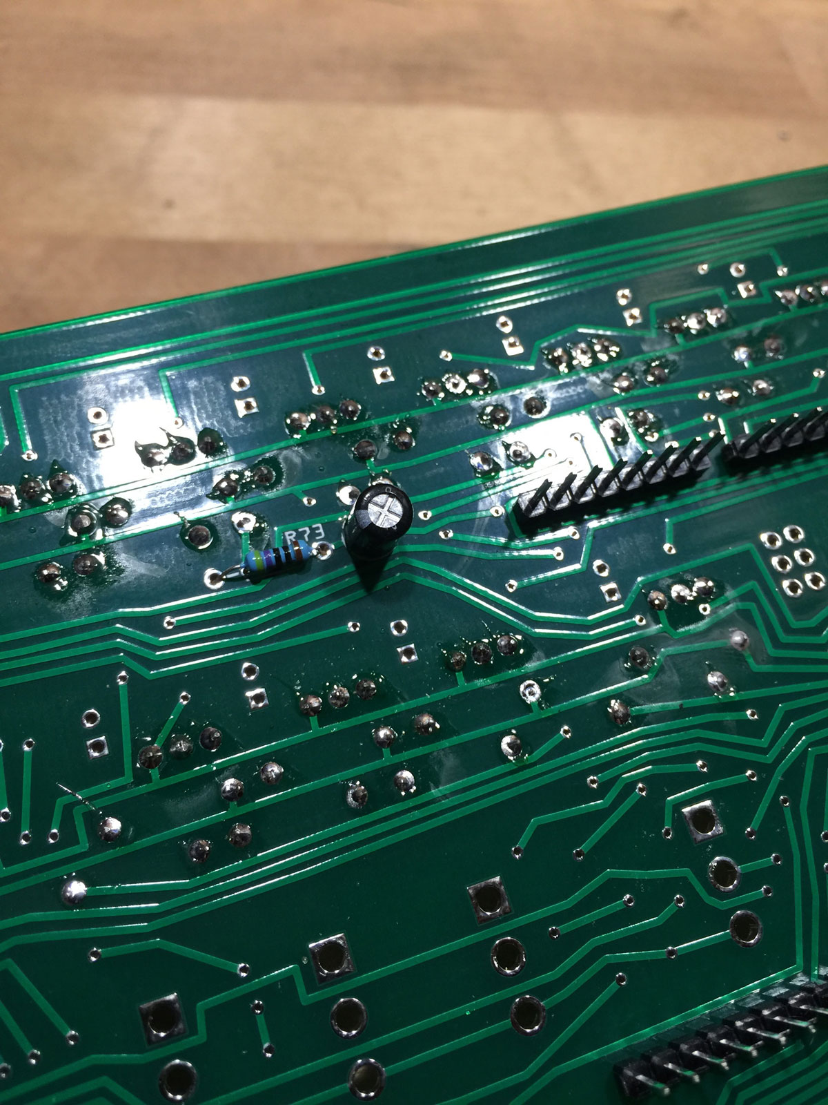
- On the underside of the board, solder the 47µF capacitor (mind the polarity – negative away from the single pin header. Next to it, solder the 470Ω resistor.
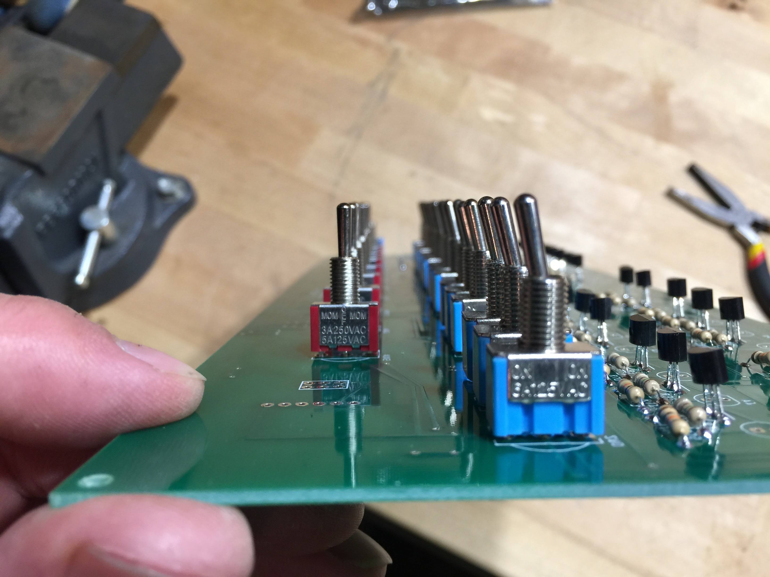
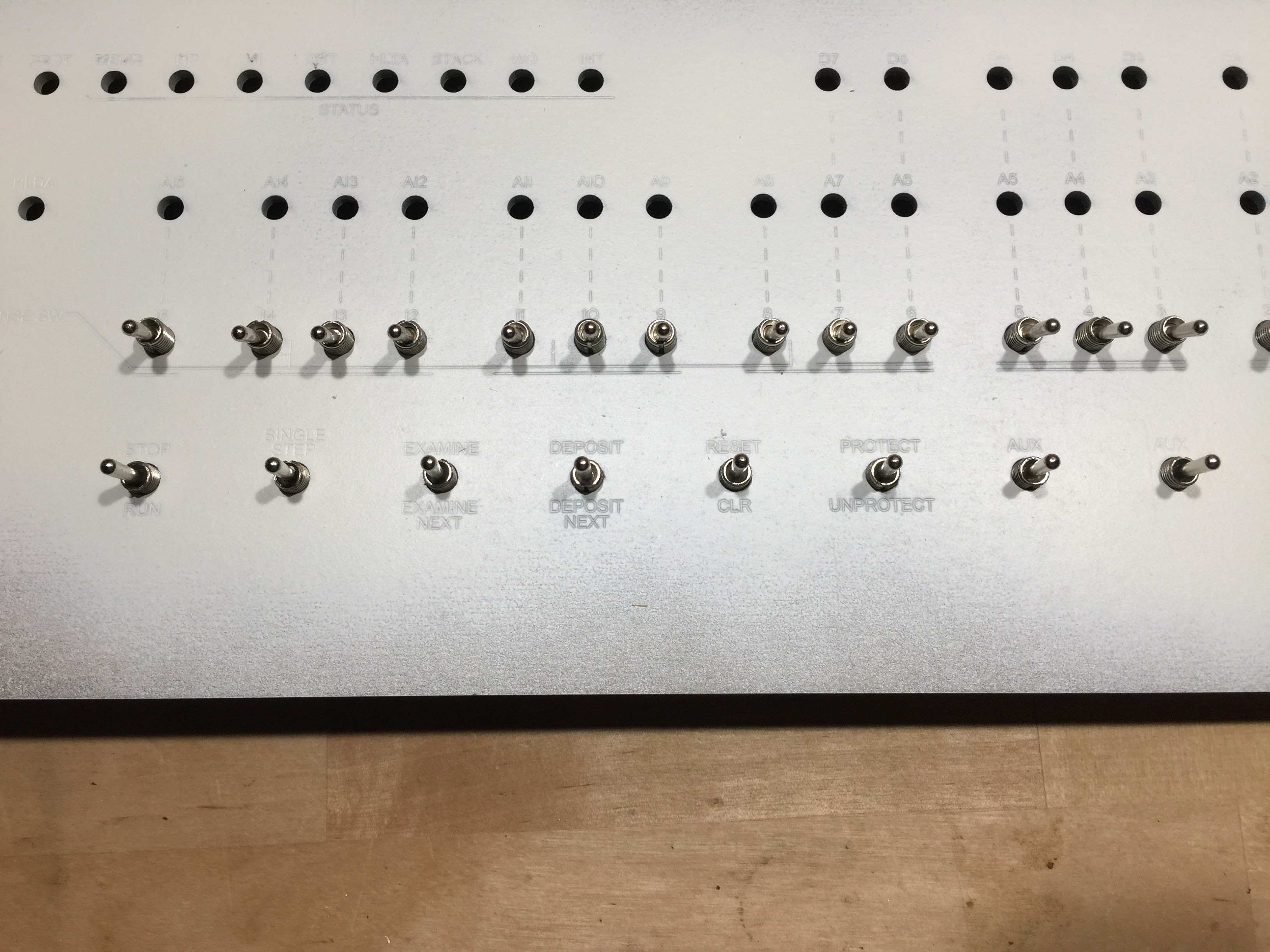
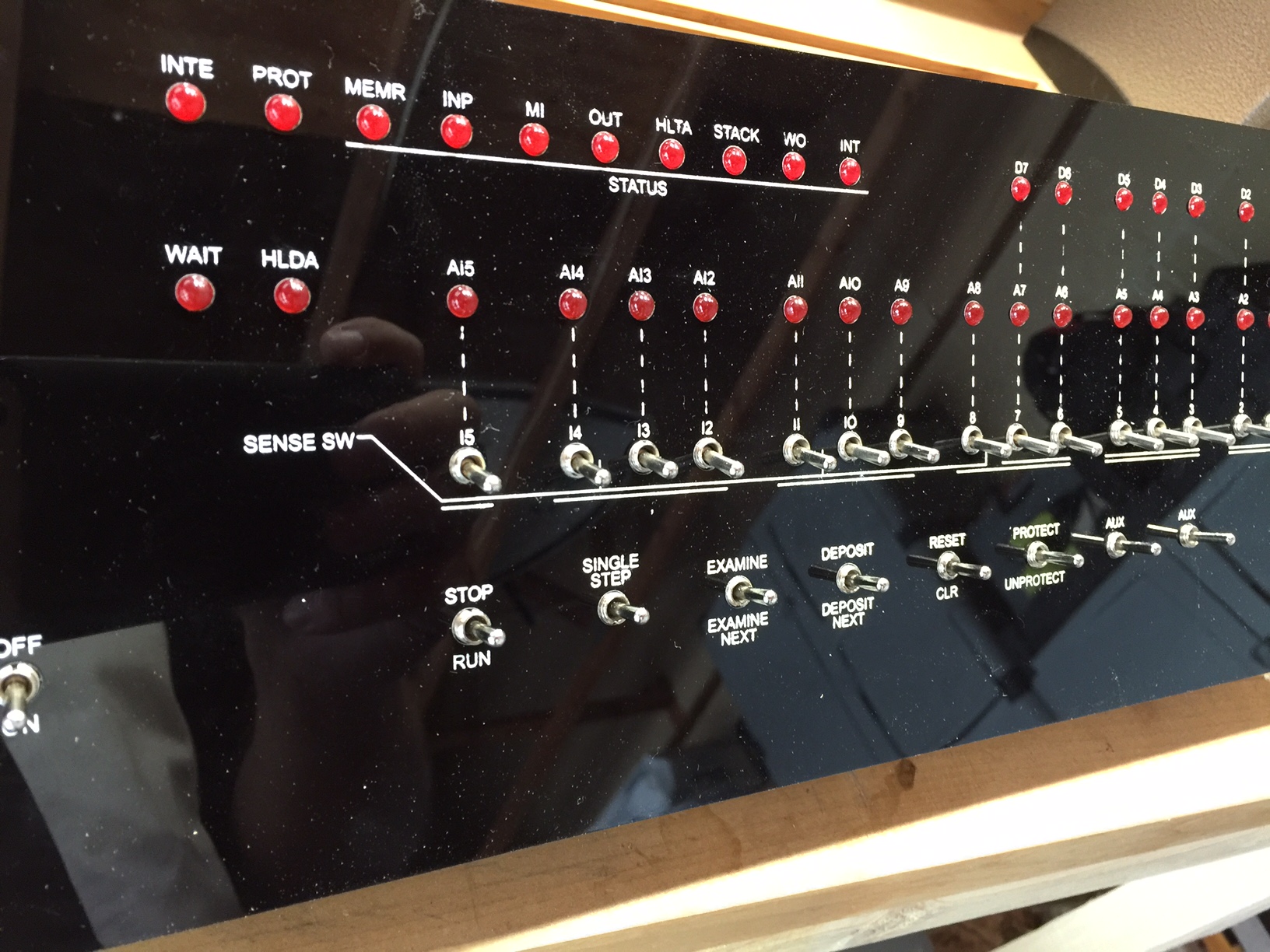
- Add the 17 on/off switches to the board in A0-A15 and the power switch. Don’t solder these into place, just put them in the board (they will fit snugly.)
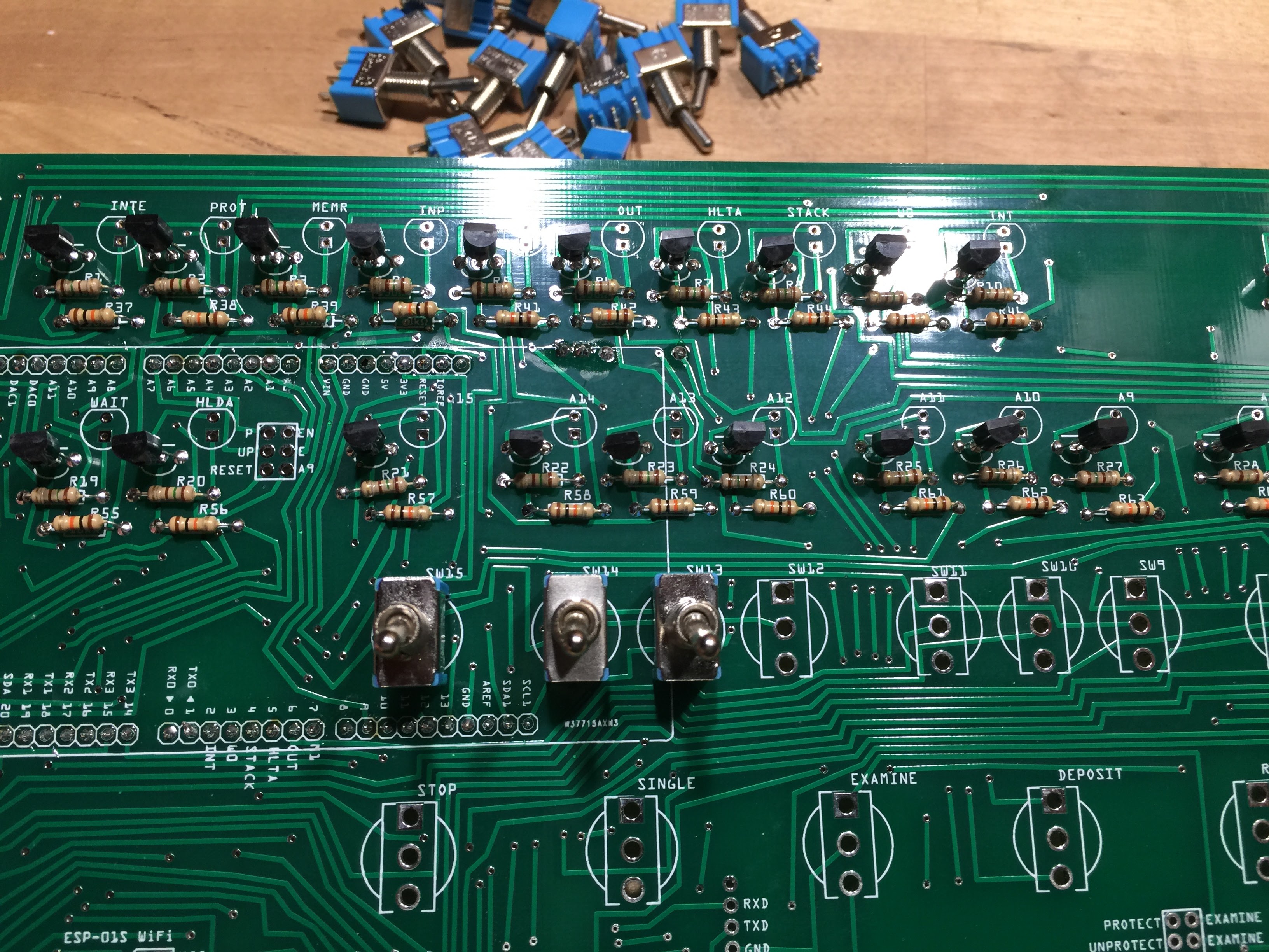
- Add the 8 three position switches to the board (Stop, Single, Examine, Deposit, Reset, Protect, Aux1, Aux2.) Again, don’t solder these into place, just put them in the board. They will fit more snugly than then the first set of switches, but can be fully inserted into the board by rocking them back and forth.
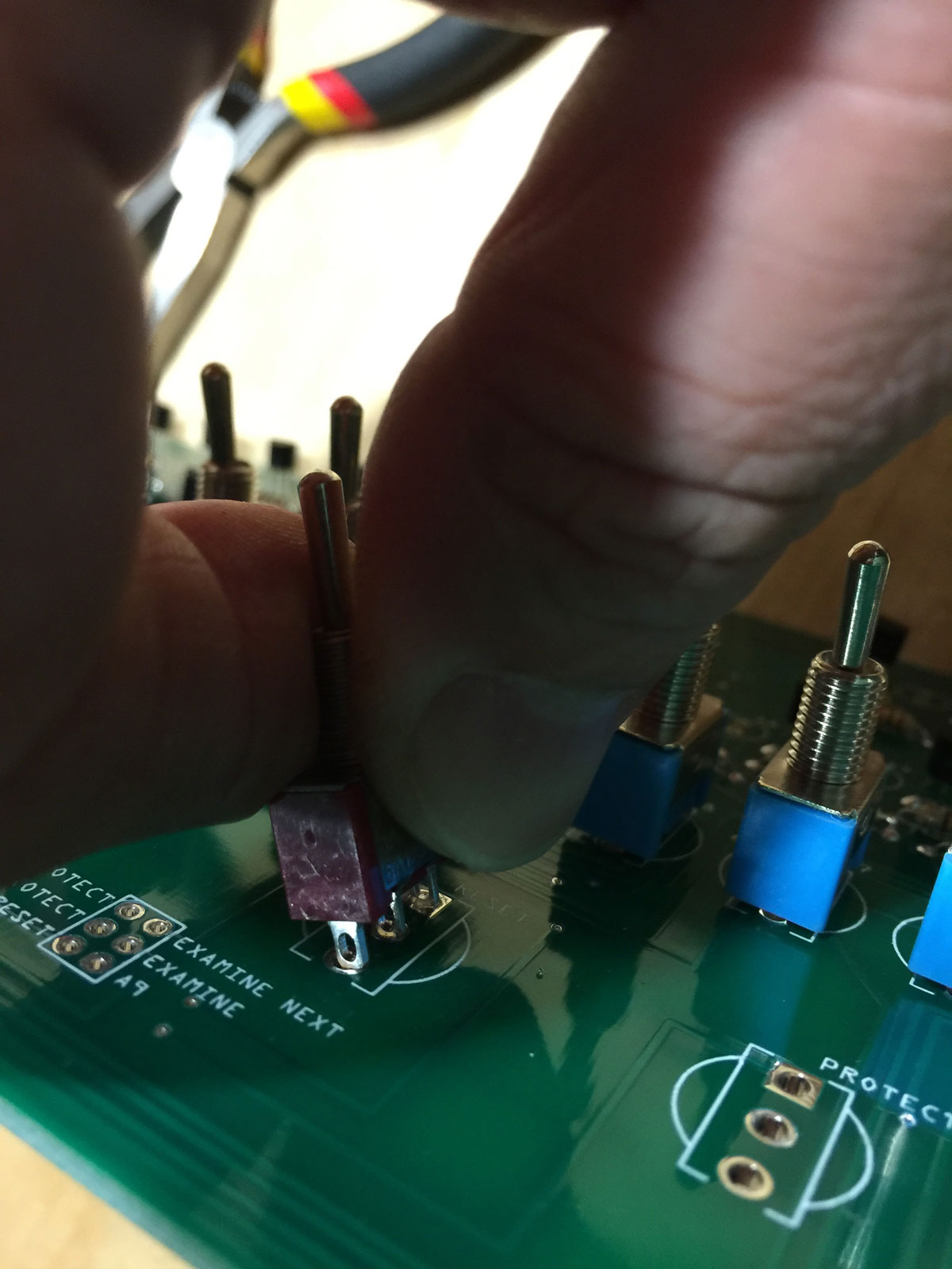
- You can also gently squeeze the lugs to more easily fit into the board, just be careful you don’t squeeze them too much, they will still need to fit snug in the PC board.
- Be sure all switches are as straight as possible and sit as low as possible on the PC board.
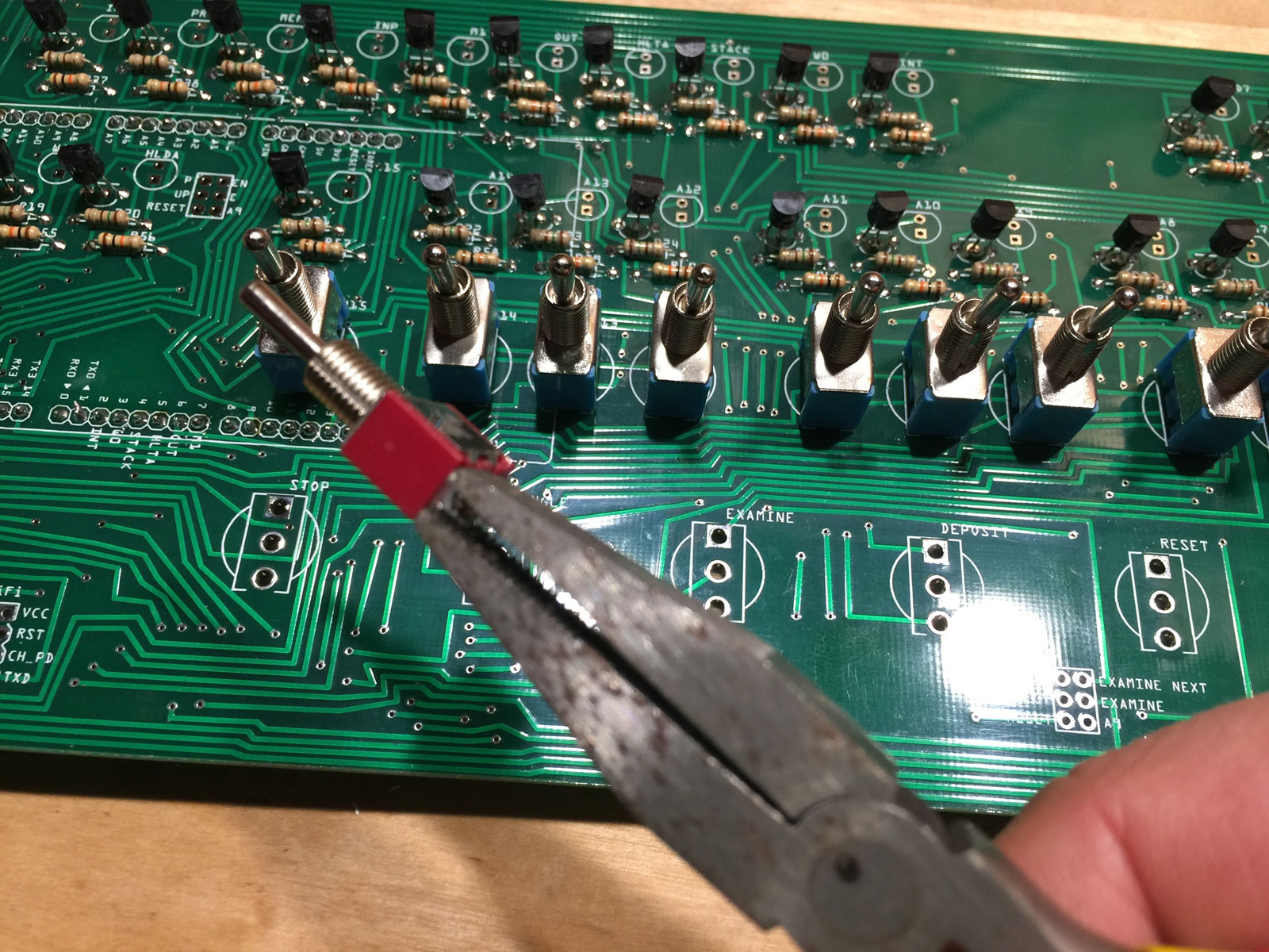
- Place the board over the switches – this will be easier if all of the A0-A15 are in the down position. This will ensure the switches are in the correct position, then you can solder them in place.
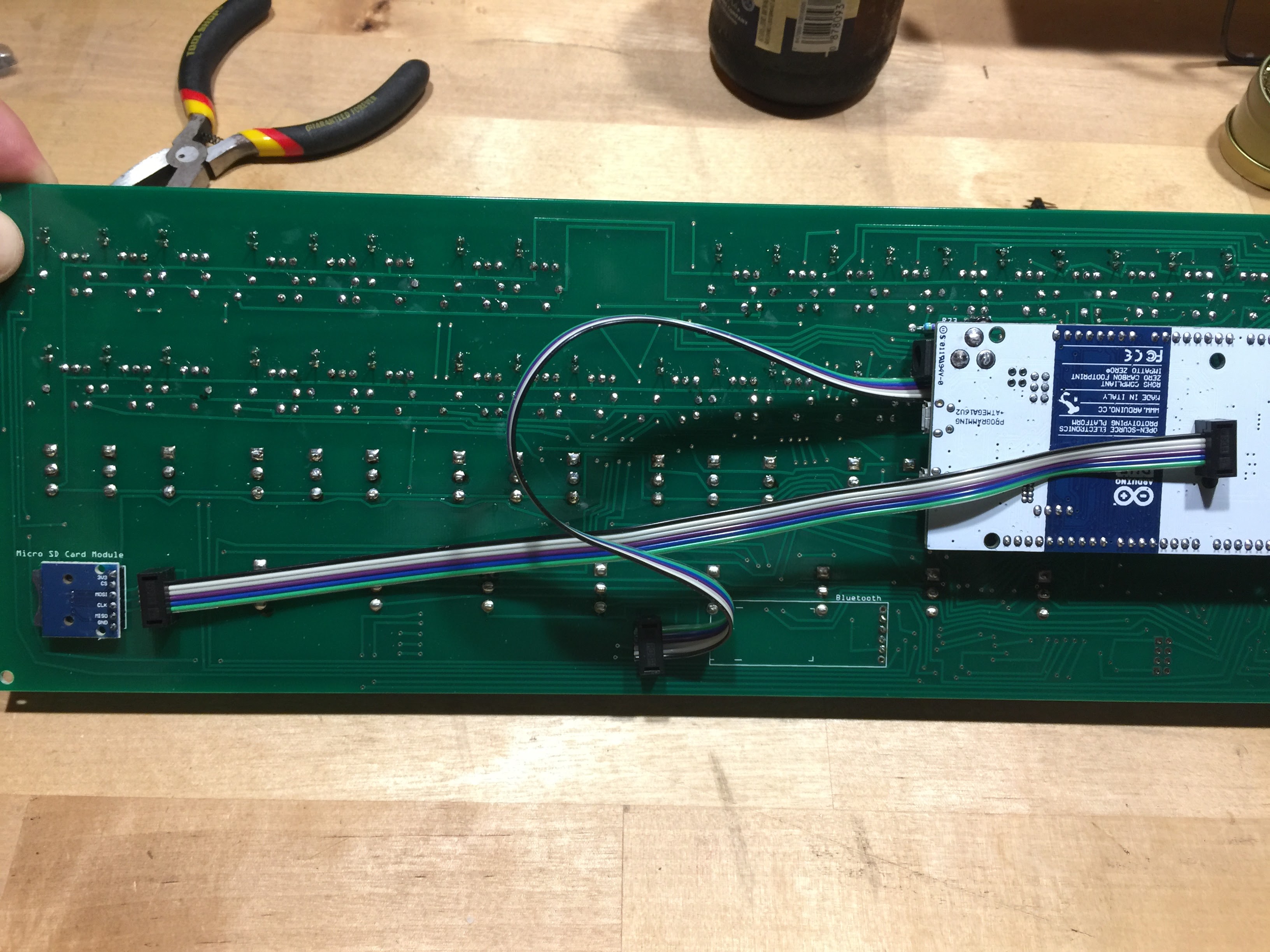
- Place one of the 6-pin cables on the underside of the PC board and solder it on the top in the orientation shown.
- Solder the other end of the 6-pin cable to the location on the bottom center of the PC board, again on the underside of the board.
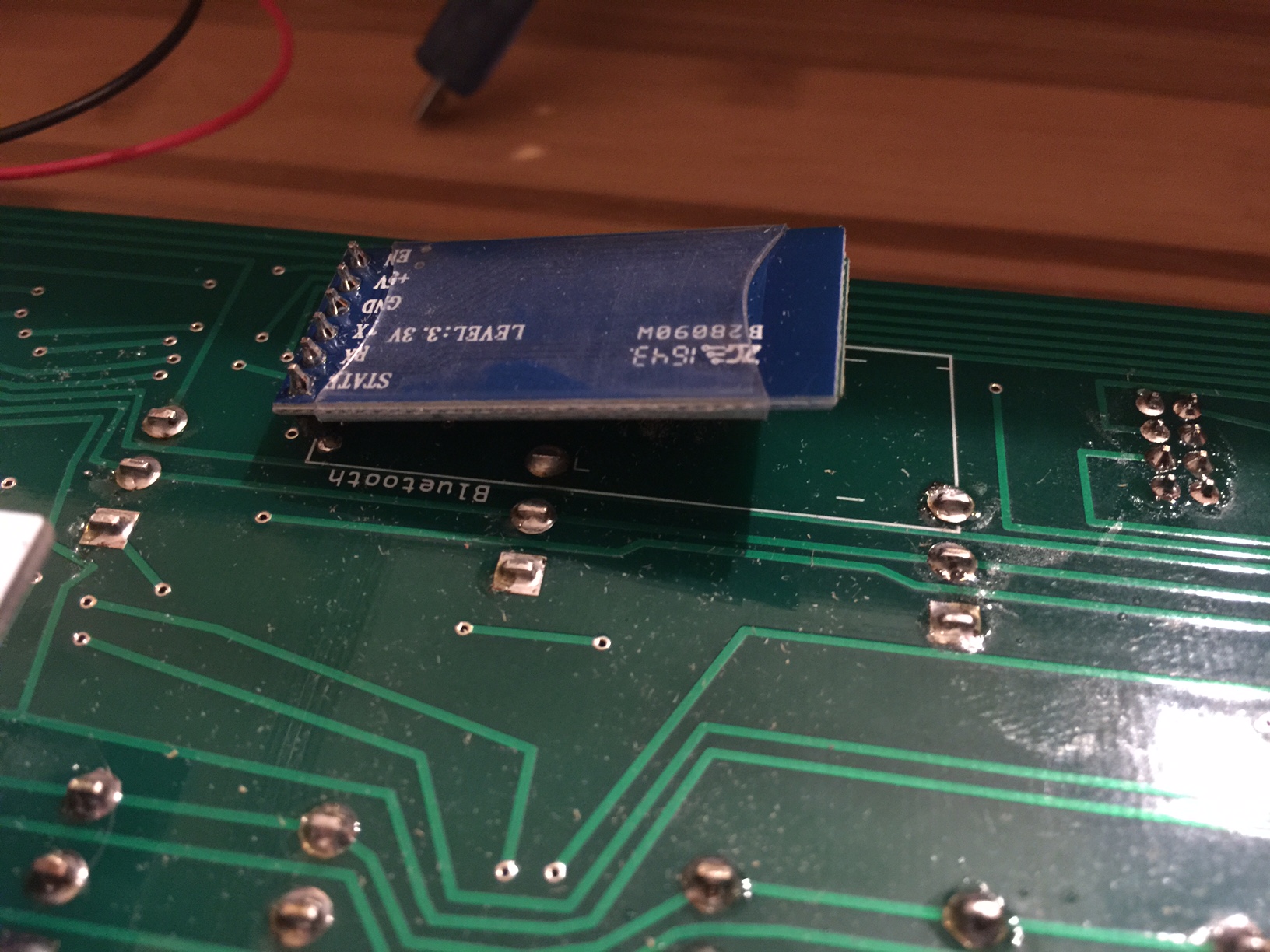
- If you have chosen the HC-05 Bluetooth module, solder that to the underside of the circuit board. You will need to gently bend the module over so the assembly will fit in the supplied project box.
Installing the Bluetooth module is certainly simpler than installing the DB9 serial module, because the Bluetooth module fits completely inside the project box.
- If you have chosen the MAX3232 DB9 serial module, solder a four-pin male header to the circuit board, in the middle of the Bluetooth connector (the Bluetooth module uses six pins, solder the header in the middle four pins.) Note: after constructing a few of these, I’d recommend soldering the header on the underside of the PC board. This is to avoid clearance problems with the cable connectors and the front panel.
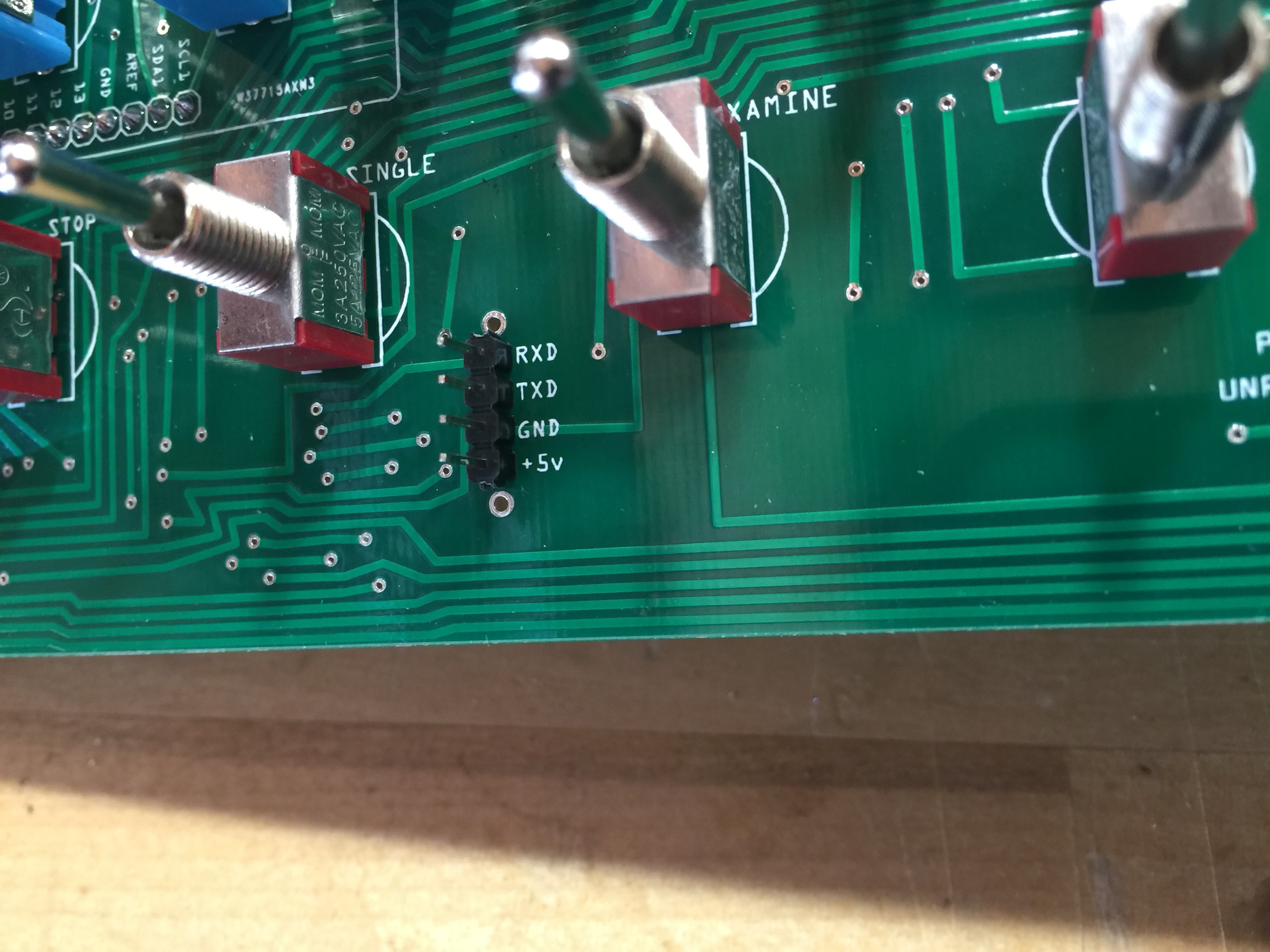
- Connect to the MAX3232 module to the four pins from the top of the board down:
MAX3232 -> PC Board
TXD -> RXD
RXD -> TXD
GND -> GND
VCC -> +5v - You are basically on your own to find a suitable location to mount the DB9 serial connector. I’ve had the best luck cutting a square hole in the back of the project box on the far right (left if looking at the back) and mounting the DB9 connector vertically. One drawback to this method is you will need a longer four-pin cable to connect the module to the PC board.
- Here’s how I (and a few others) have suggested adding the LEDs. You need to make sure they align with the front panel, so the best way to do that is to add the top row of LEDs with spacers and do not solder them in place.
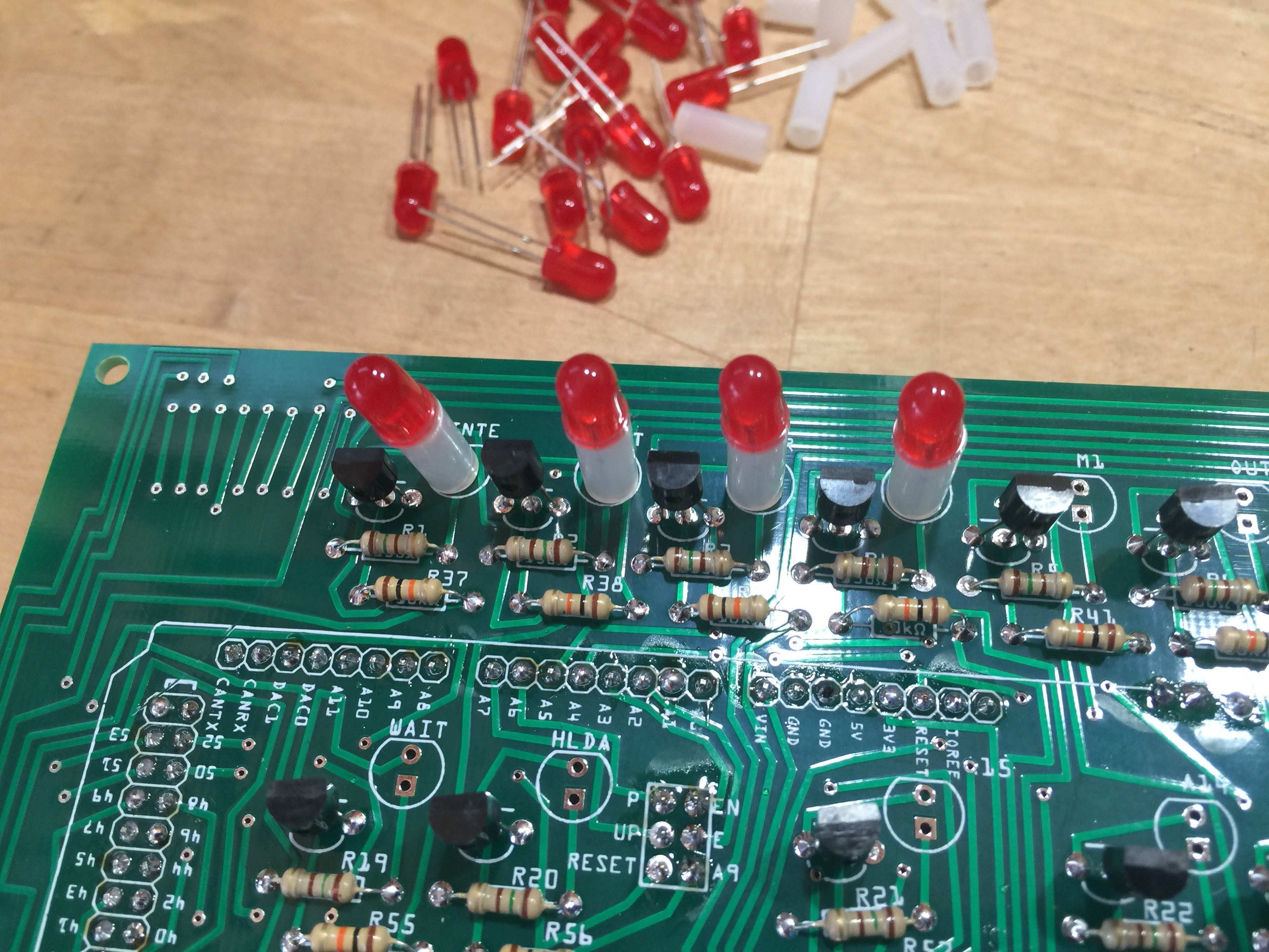
- You can then put the front panel in place and solder the LEDs. Repeat this procedure for the second row of LEDs.
If you prefer, you can simply solder the LEDs in place, and bend them into place as you put the front panel on.
- Make sure the LEDs are in the correct orientation for the polarity – the long lead should be toward the bottom of the PC board.
After you solder them, be sure to clip the excess leads under the Arduino board. If left, they can pierce the ribbon cable.
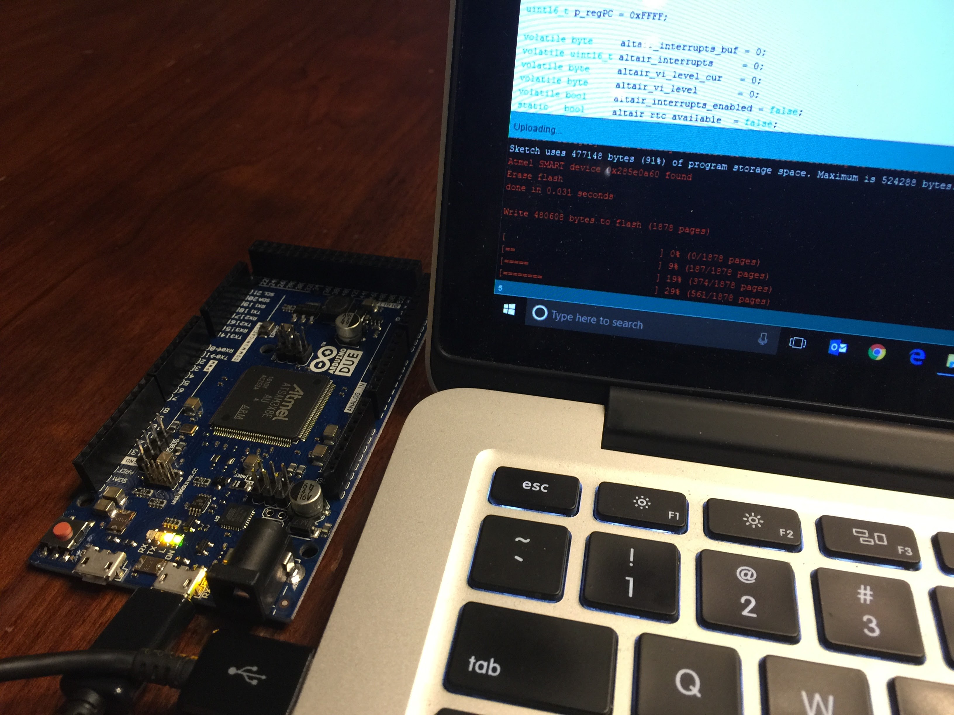
- If you haven’t already (or if you didn’t choose to have your Arduino pre-programmed) you may want to upload the programming to your Arduino now. You can find the instructions on this page.
As of version 1.2, all Arduinos will arrive pre-programmed. You can use these instructions if you want to re-program it or add your own custom programming.
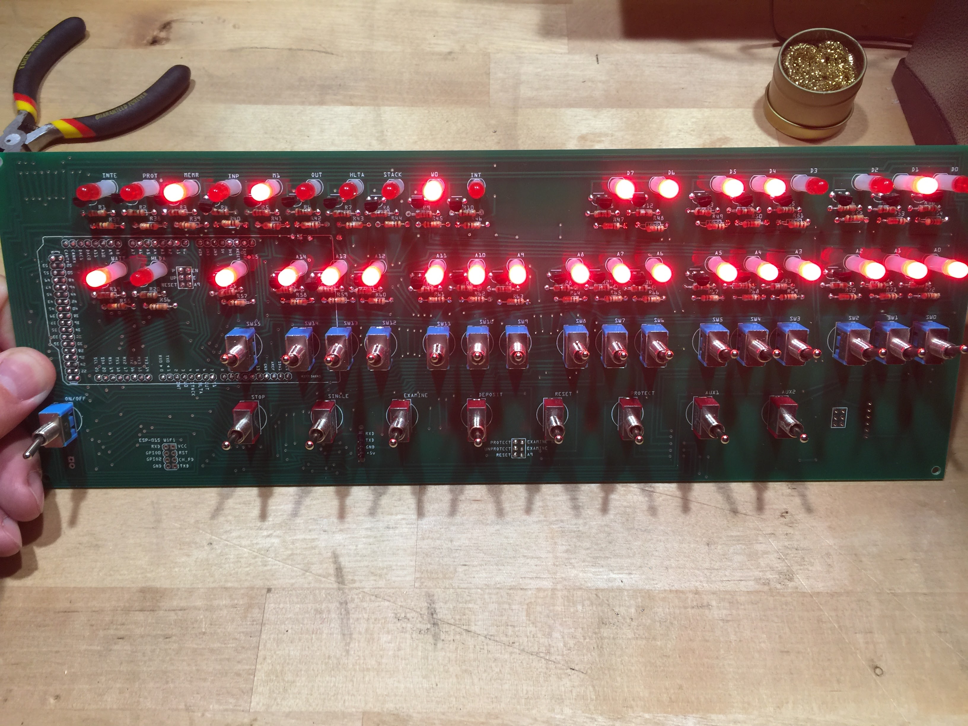
- This would be a good time to test the operation of the kit. Plug the programmed Arduino into the PC board, and insert the USB cable into the Programming port, and into a computer or USB power supply.
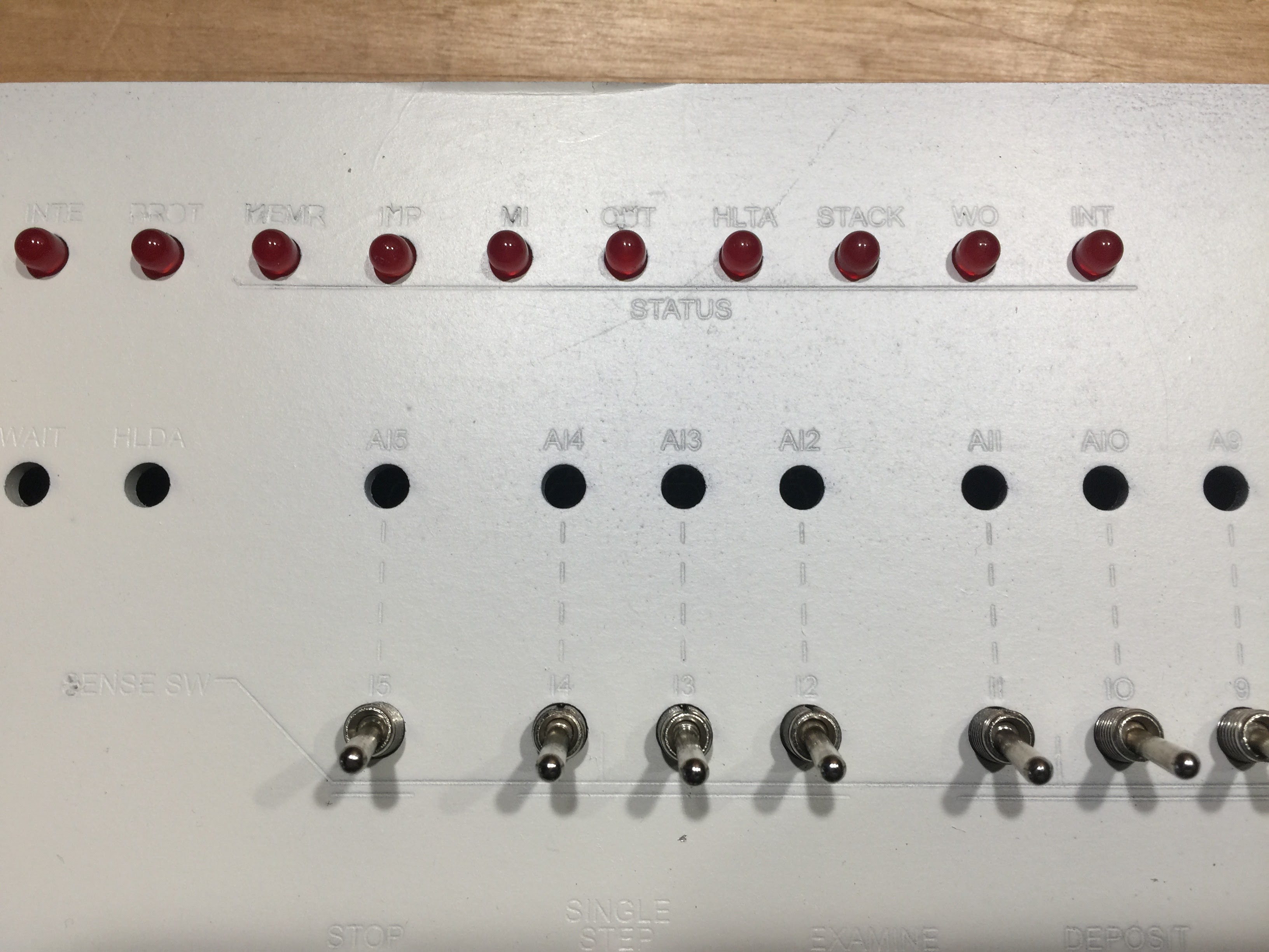
- As you apply power to the USB cable, all LEDs on the PC board should light for a second, then go dark, the a random set of LEDs will light. Test the switches at this time as well.
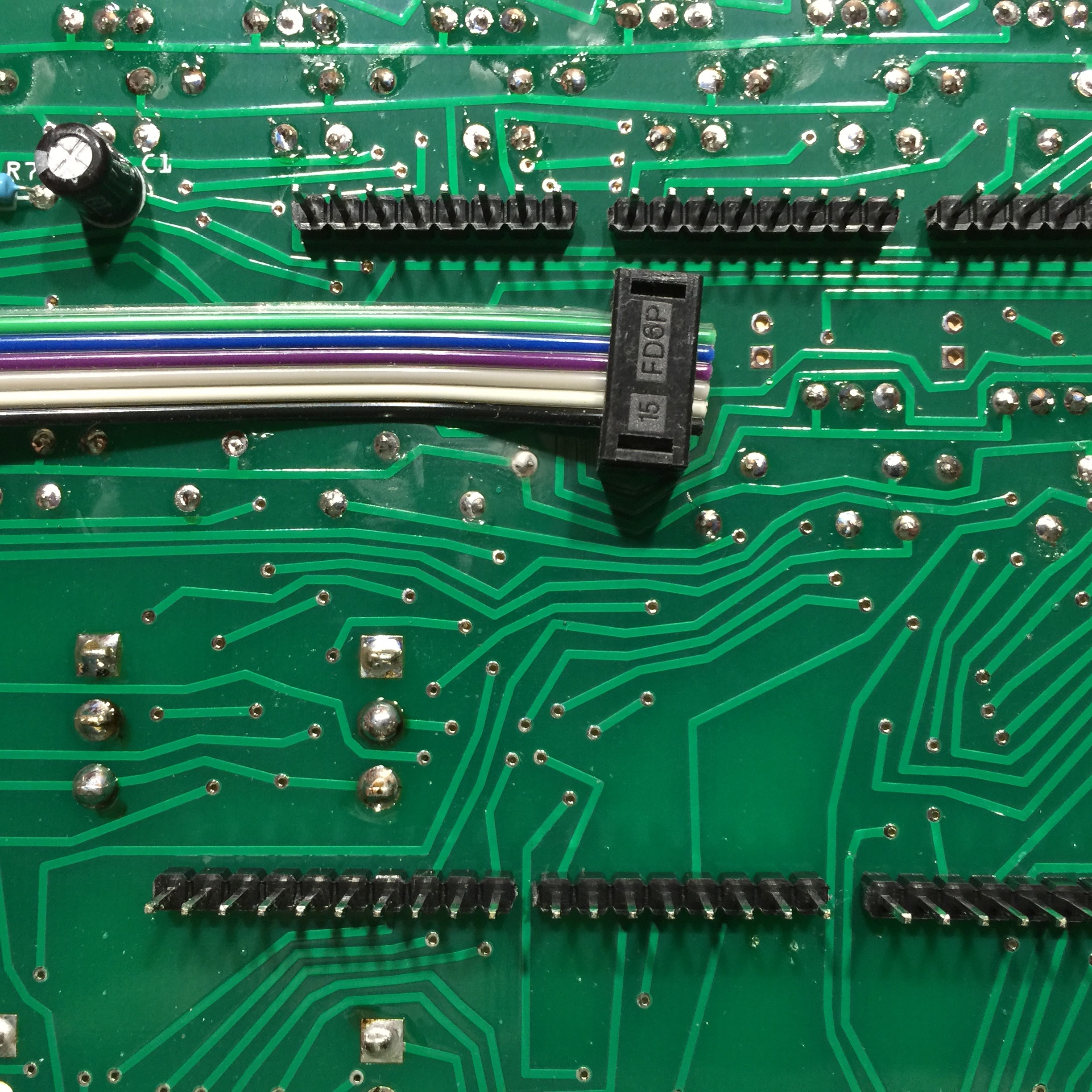
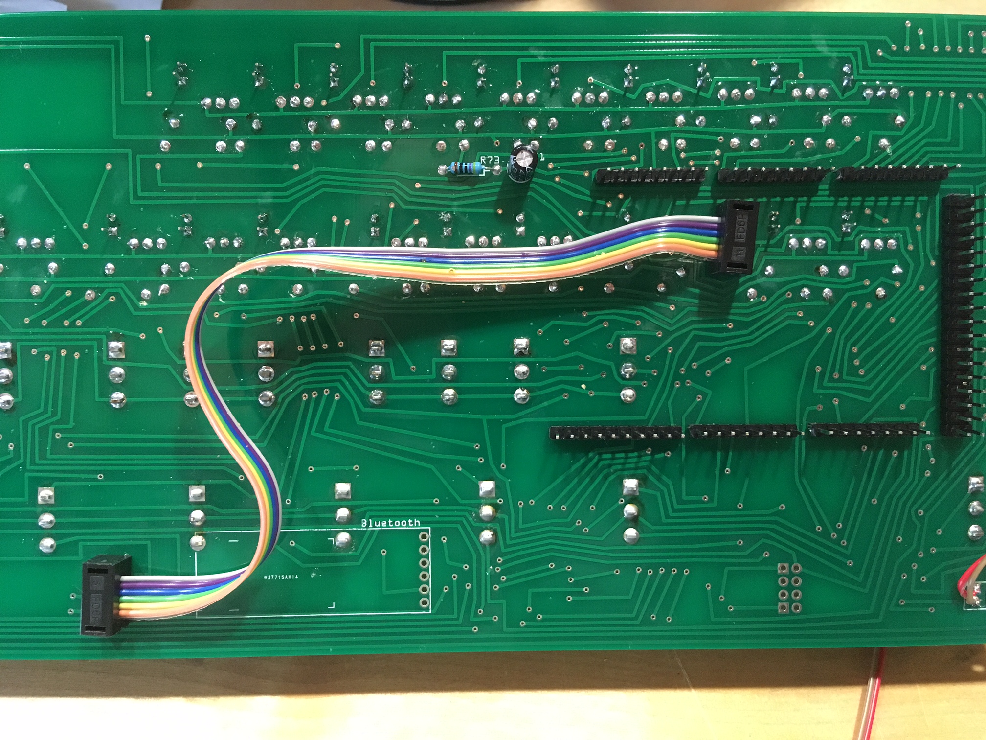
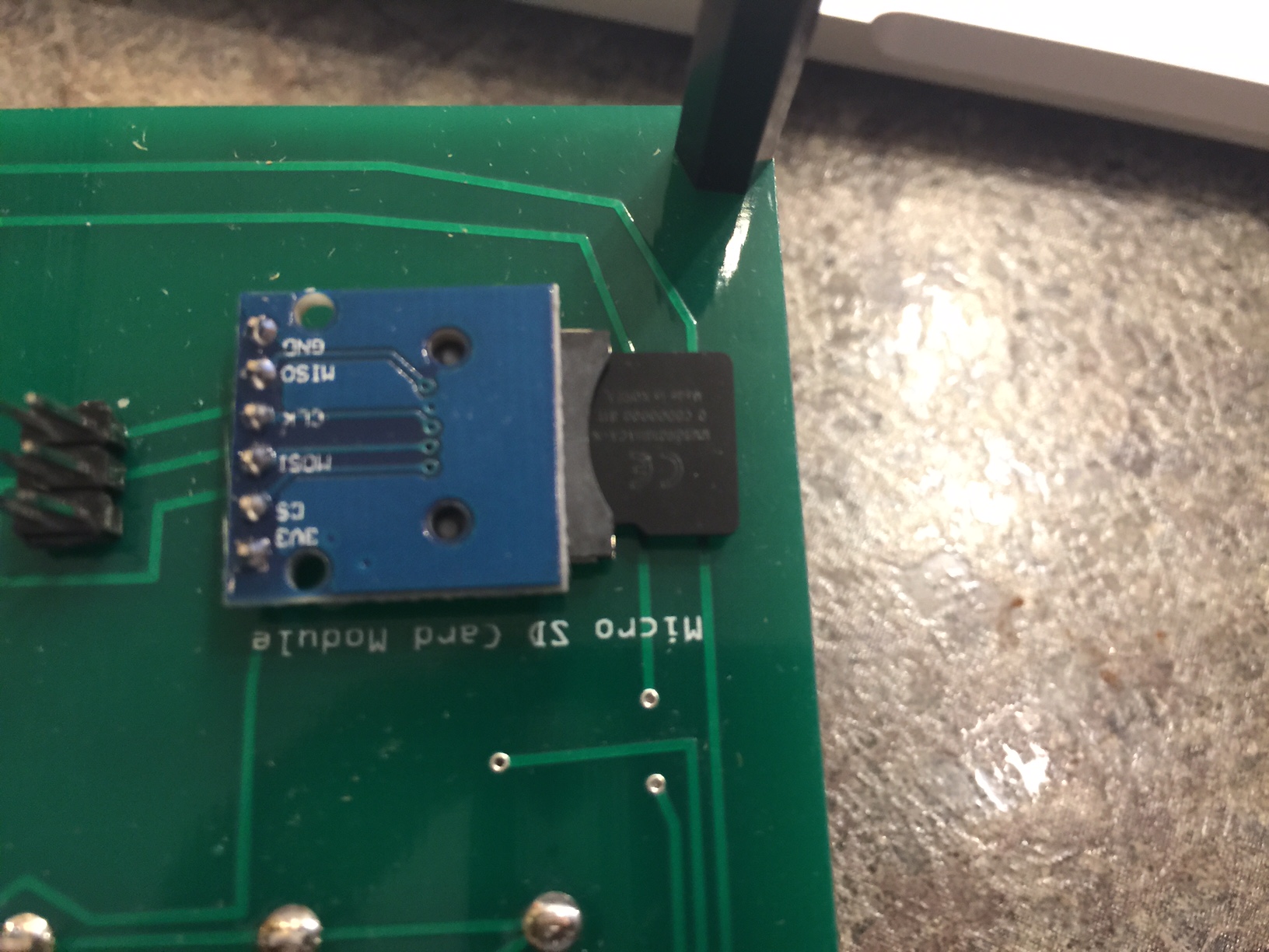
- Now remove the Arduino and attach the SD card reader to the underside of the PC board.
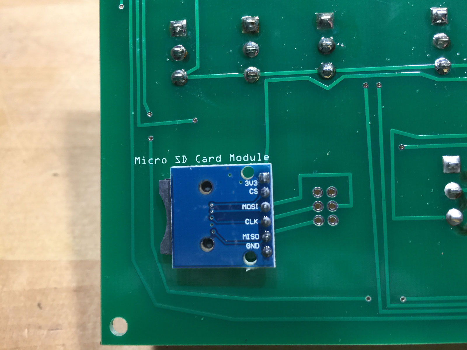
- The next part is optional, but really enhances the operation of your Arduino! You need to connect the Micro SD Module to the SPI connector on the Arduino. Unfortunately, the pins of the SPI connector are facing down toward the circuit board, where there is no room for the connector.
If you have version 1.2 of the kit, the SPI connector has already been removed and the six pin cable attached to the Arduino.
- If you’re ok desoldering the SPI connector, go ahead and do it, and attach the six pin header connector as shown in the next photo.
Again, not necessary in version 1.2 of the kit.
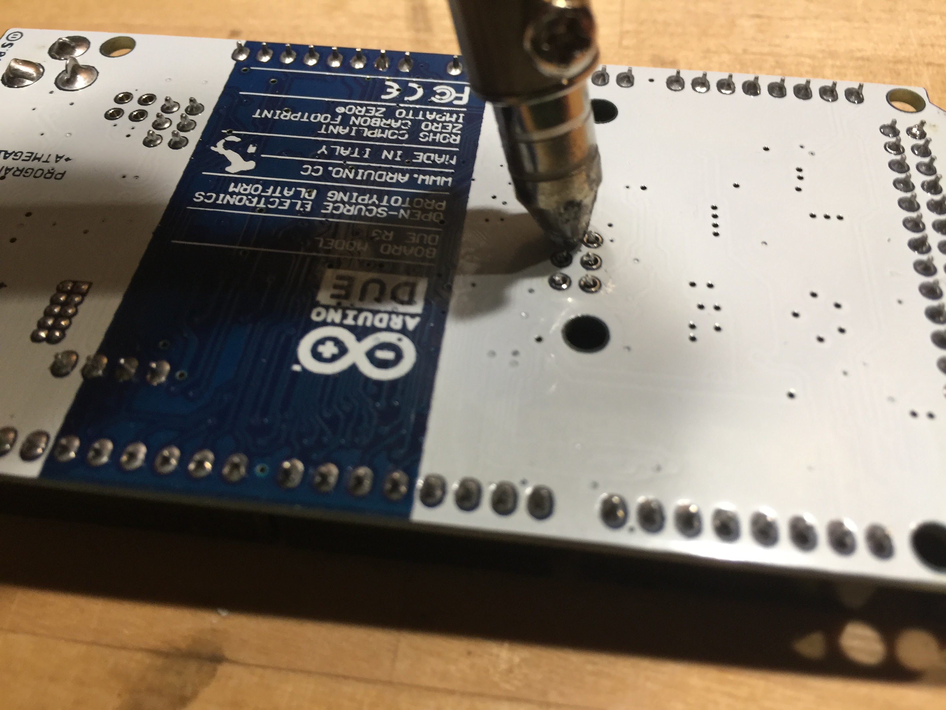
- If you don’t want to desolder the SPI connector, you can simply tack the header onto the top of the SPI pins. This will take some precision soldering, so use your smallest solder tip and a magnifier!
Again, not necessary in version 1.2 of the kit.
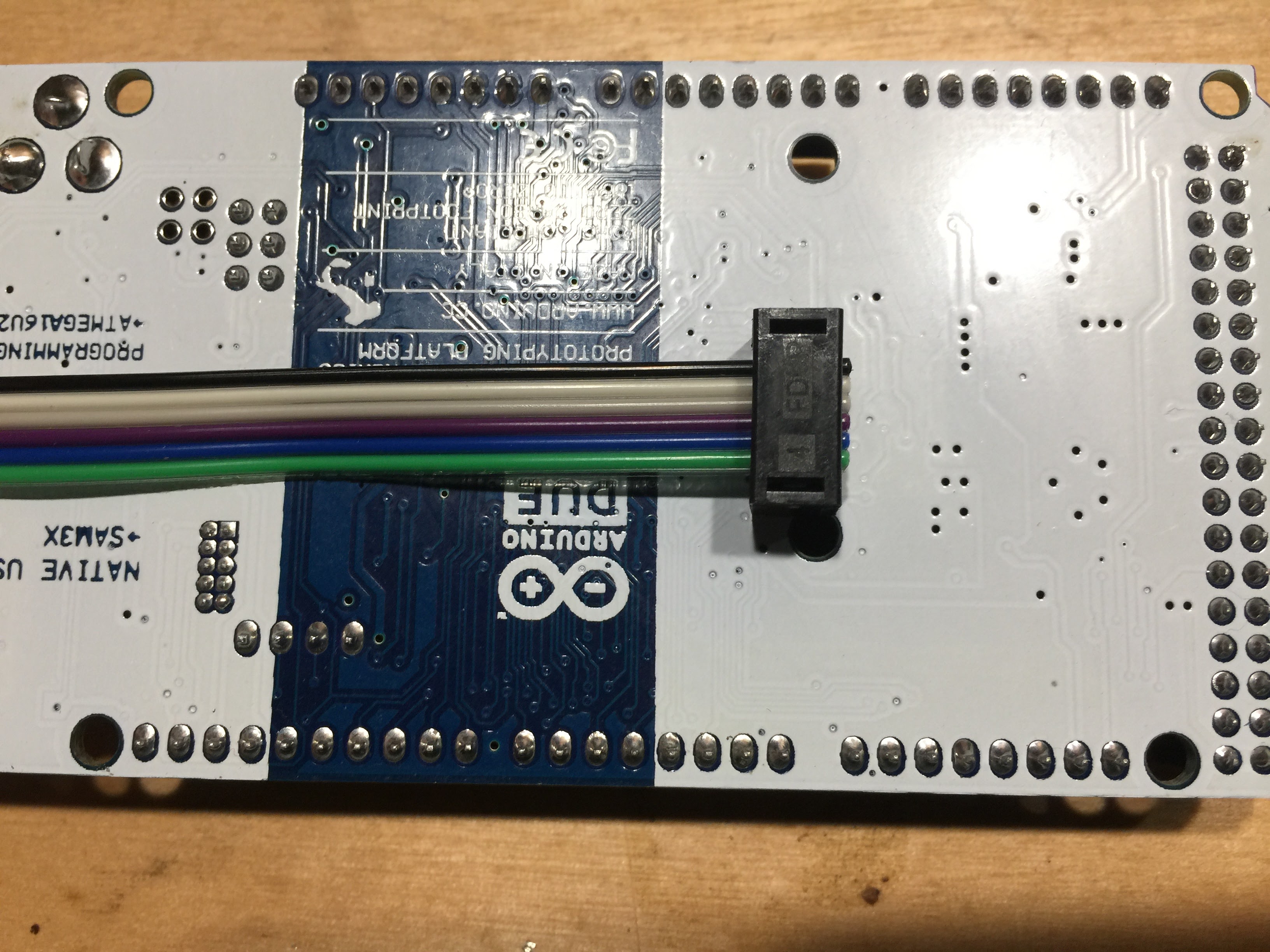
- Solder the other side of the six pin connector next to the SD Card Module.
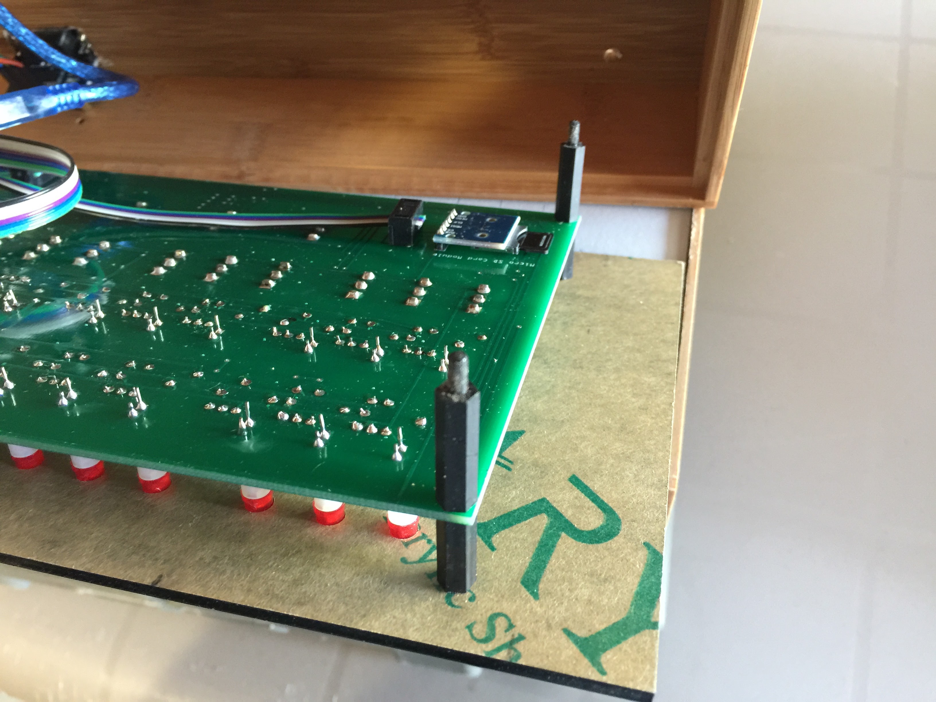
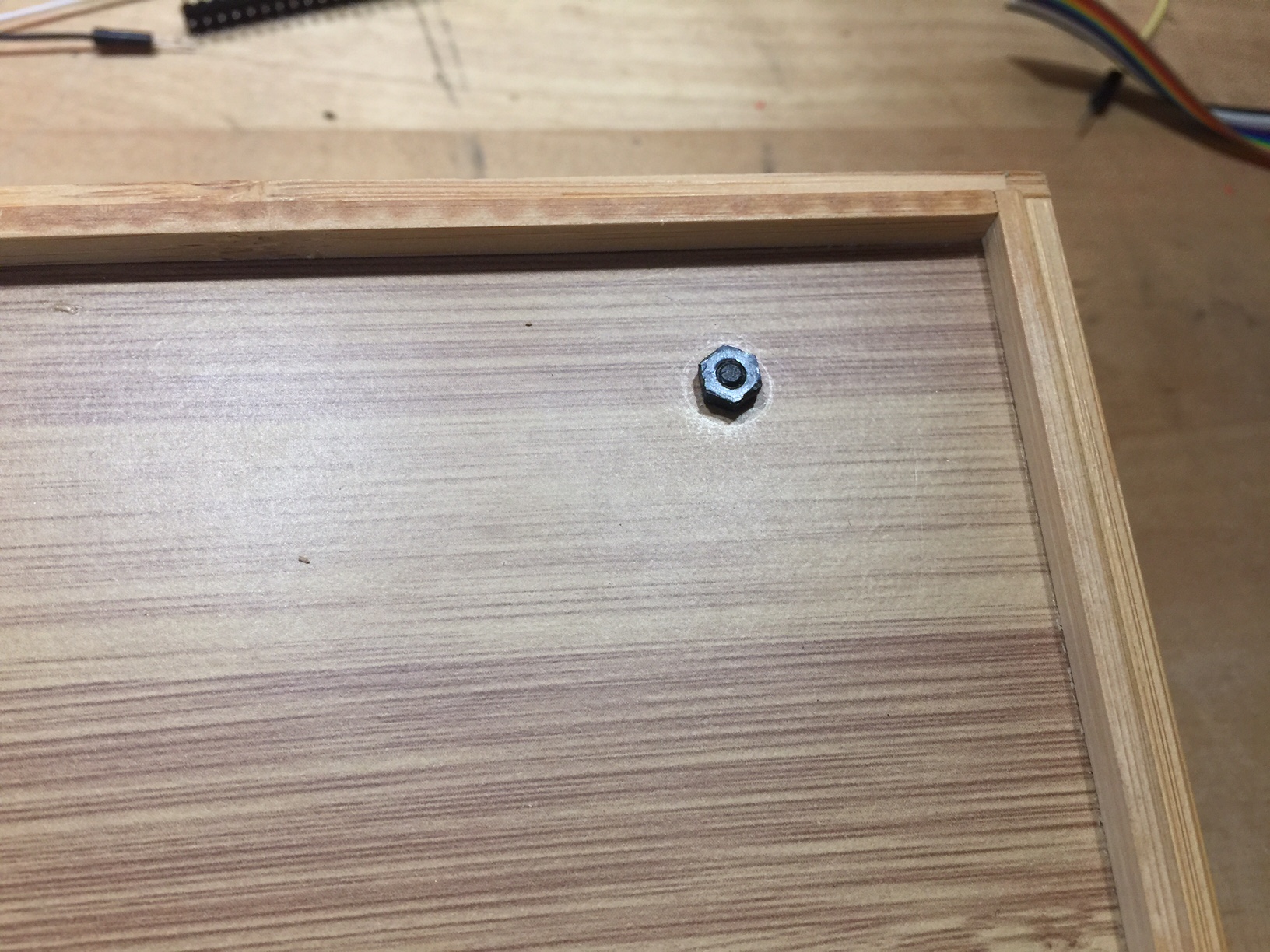
- Attach the 14mm standoff to the topside of the circuit board (with male end down) and screw it into the 20mm standoff on the underside of the circuit board.
- Place the front panel in the project case and mark the location of the four holes (I like to use a small drill bit to mark where the holes need to be.)
Drill those holes with a 1/8″ (3mm) drill bit.
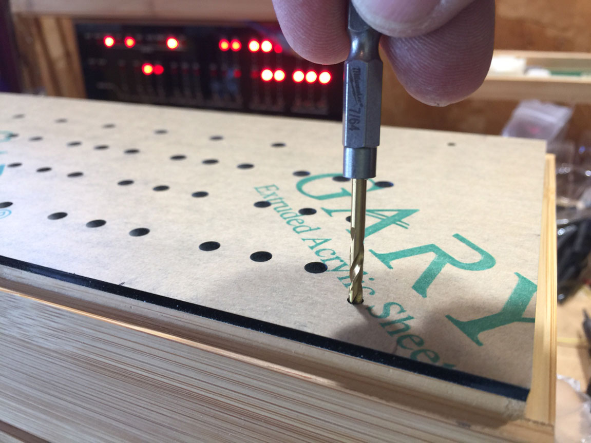
- While you’re drilling holes in the project case, drill a 1/2″ (12mm) hole in the lower left area for the DC jack.
Also drill a 1/2″ (12mm) hole a bit left of center for the USB cable.
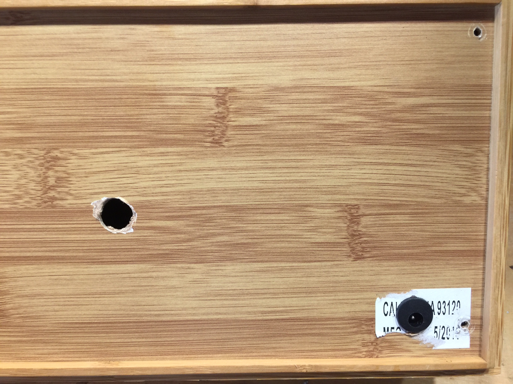
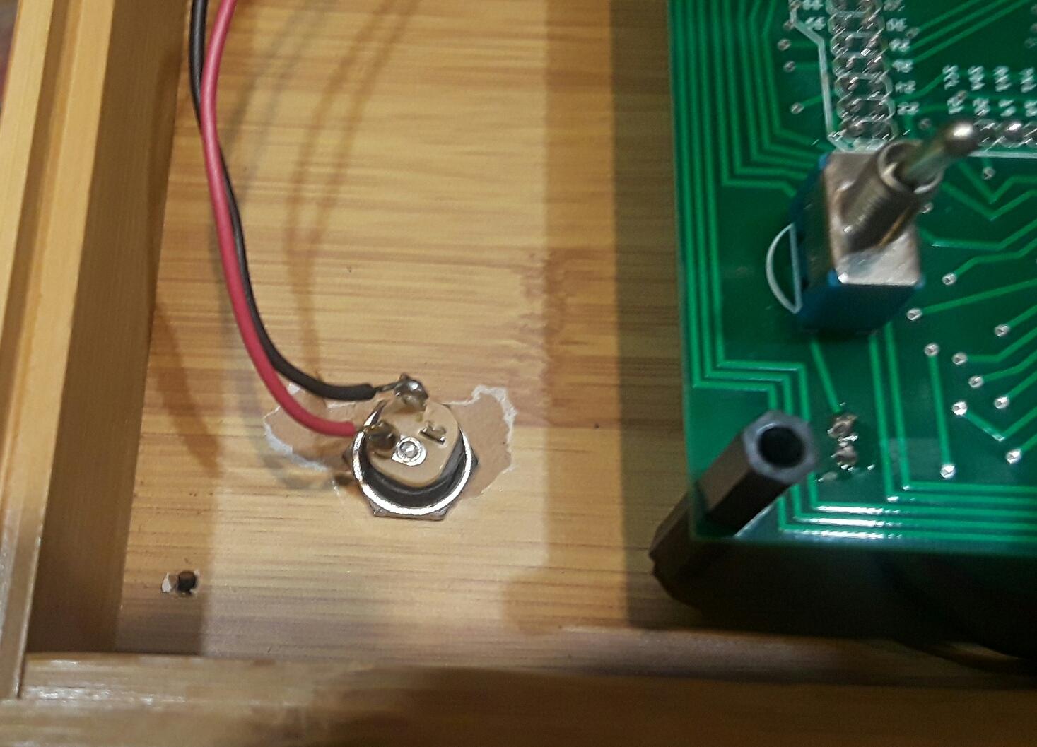
- Solder a short length of parallel stranded wire from the circuit board (lower left) to the power jack. The square solder pad is for the positive (center pin) wire. The other hole is for ground.
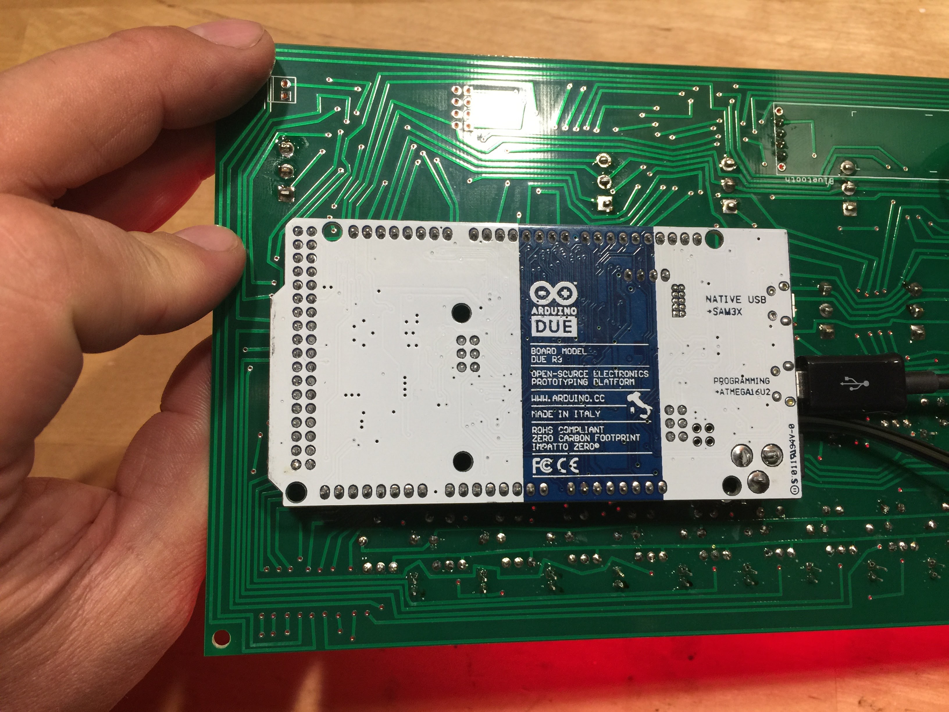
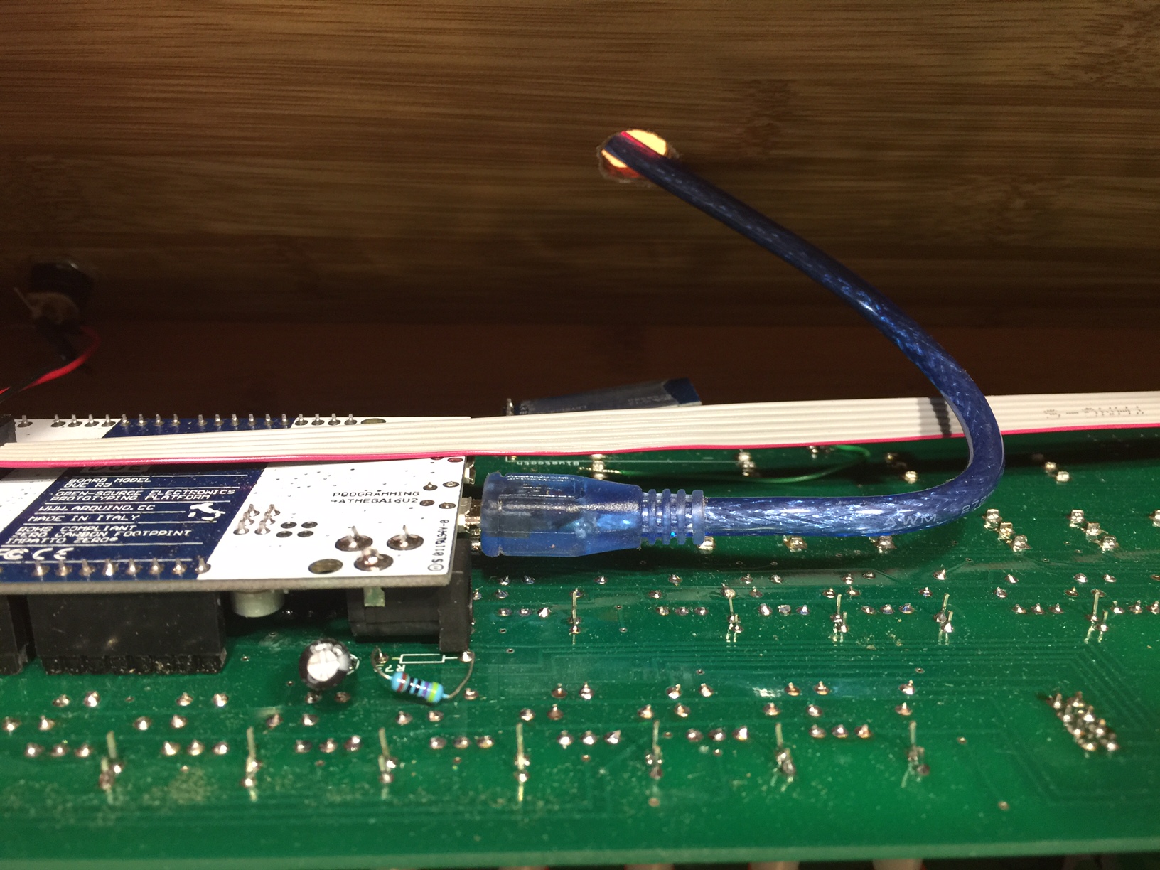
- Plug the Arduino into the circuit board, pass the USB cable through the project box and plug it into the “Programming Port”
When the Arduino is connected to a computer’s USB port, it will draw power from the port and will not need to be connected to a DC power supply.
- Remove the mask from the front panel.
I’ve found that if you remove the large piece of mask from the front panel, then soak the panel in water overnight, the rest of the mask (in the “O”, “P”, “A”, etc.) comes of fairly easy with your fingernail – in about 5 minutes you’ll have a clean panel ready to go.
Version 1.2 of the kit has a screen printed front panel, so this step is not necessary. 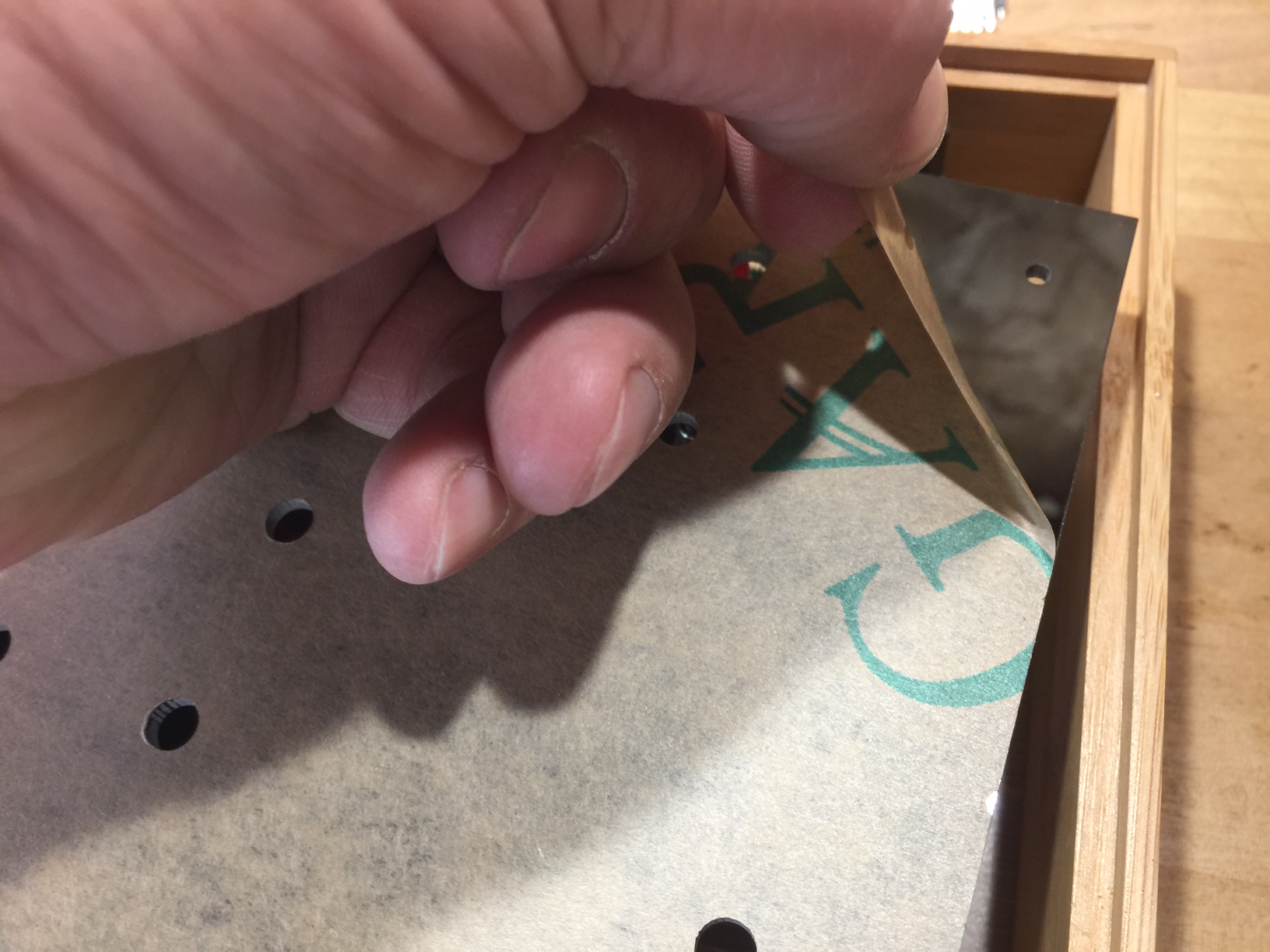
- Apply the metallic “Altair 8800” sticker.
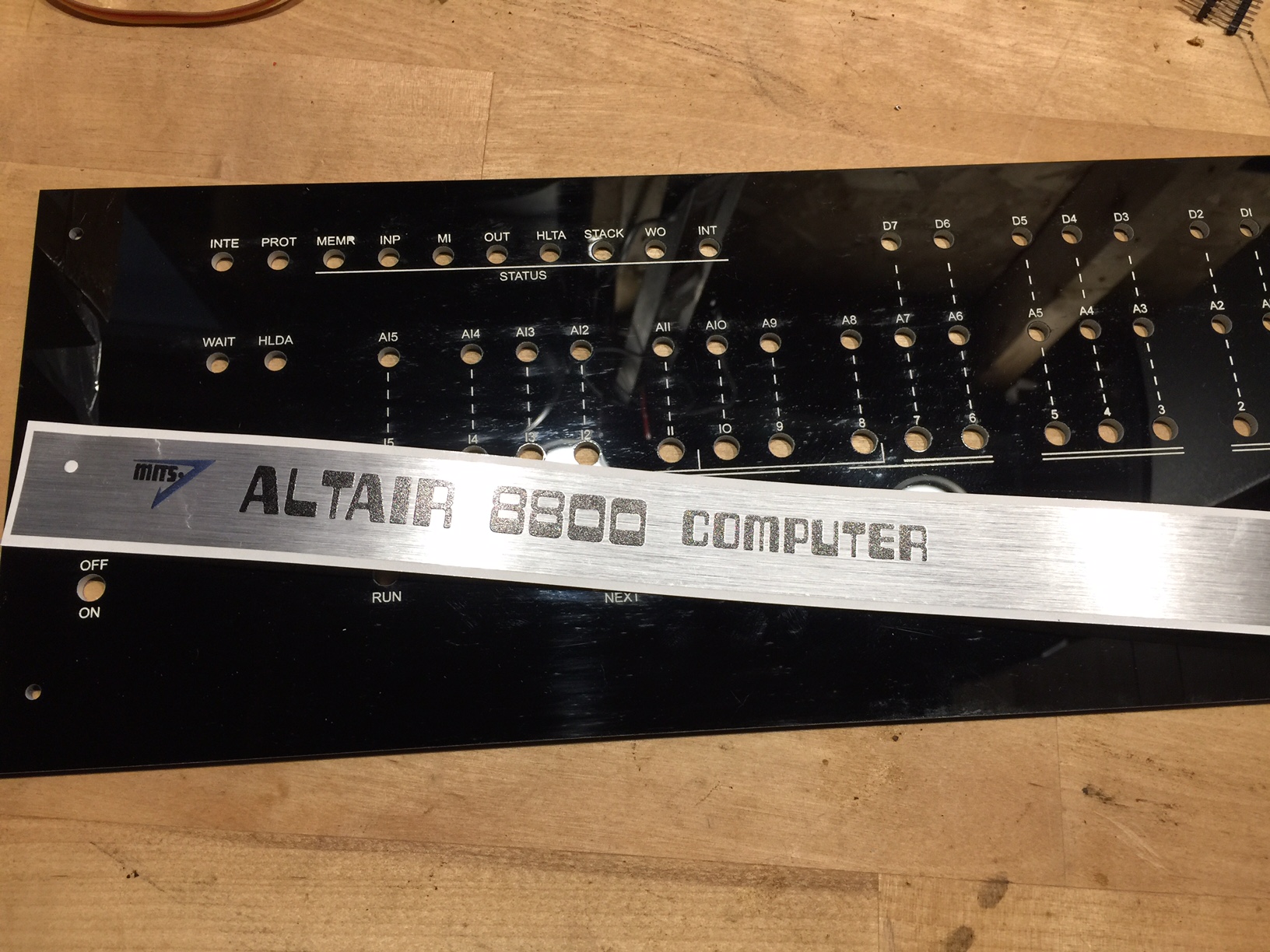
- Attach the front panel to the topside of the circuit board. Make sure the standoff holes line up, and the LEDs line up with the appropriate holes. You will probably have to apply some force, especially around the threaded switch posts. Add the 3mm nylon screws to keep the front panel in place.
- Copy the Altair disk files to an SD card (1MB is sufficient) and install the SD card in the Micro SD card module. The disk images are available here. Put the files in the root of the SD card, do not leave them in the “disks” folder. From your vantage point, the card will appear upside-down.
HINT: If you have loaded the disk images on the card and see nothing but a non-stop sequence of “c” when you access the card, you need to completely reformat the card (FAT32, be sure to select FULL format, not a quick format.) I have run into a couple circumstances where the micro SD card I was trying to use *absolutely* would not work. I don’t know why, but apparently it can happen. Then your only choice is to try a different card.
- Place the front panel/circuit board assembly into the project box. The male ends of the 20mm standoffs should protrude through the holes on the bottom of the project box. Secure it in place with 3mm nuts.
If your case seems a little tight (it’s wood so it tends to expand/contract with temperature and humidity) you can easily trim it a bit with an X-Acto knife.
Congratulations! Your Altair 8800 is complete!